Dell Latitude CPx H Service Manual - Page 43
Khupdo²&rrolqj²$vvhpeo\² - fan
 |
View all Dell Latitude CPx H manuals
Add to My Manuals
Save this manual to your list of manuals |
Page 43 highlights
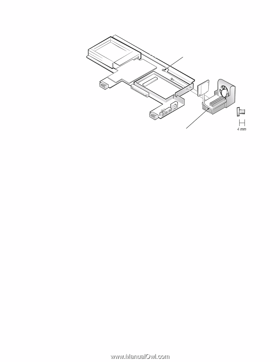
4-mm screws (2) thermal cooling assembly and exhaust fan M2.5x4 1. Remove the main battery and secondary battery (if present). 2. Remove the device from the modular bay. 3. Remove the keyboard assembly. 4. Remove the display assembly. 5. Remove the palmrest assembly. 6. Remove the microprocessor module. 7. Remove the modem (if present). 8. Remove the system board assembly. 9. Disconnect the exhaust-fan power cable from the connector on the system board. 10. Remove the two 4-mm screws securing the thermal cooling assembly and exhaust fan, and then remove the thermal cooling assembly and exhaust fan (see Figure 23). 36 Dell Latitude CPt V/CPt S Series and CPx H/CPx J Series Service Manual
-
 1
1 -
2
-
3
-
4
-
5
-
6
-
7
-
8
-
9
-
10
-
11
-
12
-
13
-
14
-
15
-
16
-
17
-
18
-
19
-
20
-
21
-
22
-
23
-
24
-
25
-
26
-
27
-
28
-
29
-
30
-
31
-
32
-
33
-
34
-
35
-
36
-
37
-
 38
38 -
 39
39 -
 40
40 -
 41
41 -
 42
42 -
 43
43 -
 44
44 -
 45
45 -
 46
46 -
 47
47 -
 48
48
 |
 |
36
Dell Latitude CPt V/CPt S Series and CPx H/CPx J Series Service Manual
7KHUPDO²&RROLQJ²$VVHPEO\²
)LJXUH²¸¹¶²²7KHUPDO²&RROLQJ²$VVHPEO\²5HPRYDO
127,&(±²7R²DYRLG²GDPDJLQJ²WKH²V\VWHP²ERDUG´²\RX²PXVW²UHPRYH²WKH²
PDLQ²EDWWHU\²EHIRUH²\RX²VHUYL³H²WKH²³RPSXWHU
1.
Remove the main battery and secondary battery (if present).
2.
Remove the device from the modular bay.
3.
Remove the keyboard assembly.
4.
Remove the display assembly.
5.
Remove the palmrest assembly.
6.
Remove the microprocessor module.
7.
Remove the modem (if present).
8.
Remove the system board assembly.
9.
Disconnect the exhaust-fan power cable from the connector on the system
board.
10. Remove the two 4-mm screws securing the thermal cooling assembly and
exhaust fan, and then remove the thermal cooling assembly and exhaust
fan (see Figure 23).
4-mm screws (2)
thermal cooling
assembly and exhaust fan
M2.5x4