Dell Latitude CPx H Service Manual - Page 40
Rghp²$vvhpeo
 |
View all Dell Latitude CPx H manuals
Add to My Manuals
Save this manual to your list of manuals |
Page 40 highlights
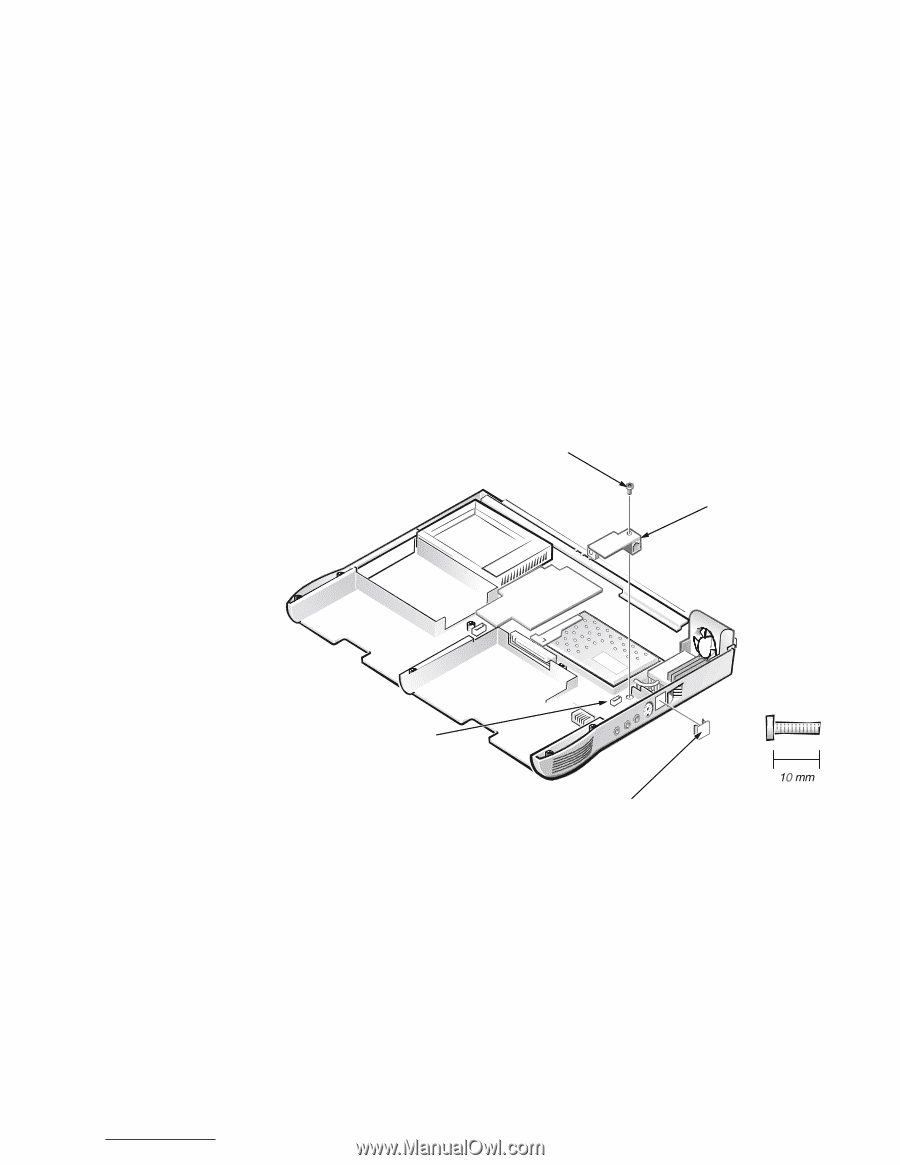
The modem assembly is optional. The modem (if present) must be removed before the main system board can be removed (see Figure 21). 1. Remove the main battery and secondary battery (if present). 2. Remove the keyboard assembly. 3. Remove the display assembly. 4. Remove the palmrest assembly. 5. Remove the 10-mm screw and washer securing the modem assembly (see Figure 21). 10-mm screw internal modem system board connector for the modem case plug for modem M2.5x10 1. Press the RJ11 connector of the modem assembly into the hole in the bottom case assembly. 2. Carefully align and press the modem into the system board connector. 3. Replace the internal modem 10-mm screw and washer (see Figure 21). support.dell.com Dell Latitude CPt V/CPt S Series and CPx H/CPx J Series Service Manual 33
-
 1
1 -
2
-
3
-
4
-
5
-
6
-
7
-
8
-
9
-
10
-
11
-
12
-
13
-
14
-
15
-
16
-
17
-
18
-
19
-
20
-
21
-
22
-
23
-
24
-
25
-
26
-
27
-
28
-
29
-
30
-
31
-
32
-
33
-
34
-
 35
35 -
 36
36 -
 37
37 -
 38
38 -
 39
39 -
 40
40 -
 41
41 -
 42
42 -
 43
43 -
 44
44 -
 45
45 -
46
-
47
-
48
 |
 |