Dell Latitude CSx H Service Manual - Page 19
the bottom case see
 |
View all Dell Latitude CSx H manuals
Add to My Manuals
Save this manual to your list of manuals |
-
 1
1 -
2
-
3
-
4
-
5
-
6
-
7
-
8
-
9
-
10
-
11
-
12
-
13
-
 14
14 -
 15
15 -
 16
16 -
 17
17 -
 18
18 -
 19
19 -
 20
20 -
 21
21 -
 22
22 -
 23
23 -
 24
24 -
25
-
26
-
27
-
28
-
29
-
30
-
31
-
32
-
33
-
34
-
35
-
36
-
37
-
38
-
39
-
40
-
41
-
42
-
43
-
44
 |
 |

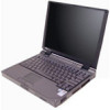
Dell Latitude CS Portable Computers Service Manual
11
’LVSOD\±$VVHPEO\±
)LJXUH±µÀ¶±±’LVSOD\±$VVHPEO\±5HPRYDO
127,&(±²7R²DYRLG²GDPDJLQJ²WKH²V\VWHP²ERDUG´²\RX²PXVW²UHPRYH²WKH²
EDWWHU\²EHIRUH²\RX²VHUYLFH²WKH²FRPSXWHU³
1.
Remove the status indicator panel.
2.
Remove the right plastic hinge cover by sliding it to the right of the display
assembly.
3.
Remove the two M2.6 x 6-mm hinge screws that secure the right hinge to
the bottom case (see Figure 10).
4.
Remove the left plastic hinge cover by sliding it to the left of the display
assembly.
status indicator
panel
display assembly
M2.6 x 6-mm
screws (4)
left hinge cover
right hinge cove
display-assembly
interface wire
display-assembly
inverter wire