Dell Latitude E7240 Owner's Manual - Page 18
Installing the Wi‐Fi Switch Board, Removing the Memory Module - memory slot
 |
View all Dell Latitude E7240 manuals
Add to My Manuals
Save this manual to your list of manuals |
Page 18 highlights
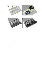
d) keyboard trim e) keyboard f) palmrest 3. Disconnect the wi-fi switch board cable from the system board and remove the screw that secures the wi-fi swtich board to the computer. Remove the wi-fi switch board. Installing the Wi‐Fi Switch Board 1. Insert the wi-fi switch board in its slot. 2. Connect the wi-fi switch board to the system board. 3. Tighten the screw that secures the wi-fi switch board to the system board. 4. Install: a) palmrest b) keyboard c) keyboard trim d) base cover e) battery f) SD card 5. Follow the procedures in After Working Inside Your Computer. Removing the Memory Module 1. Follow the procedures in Before Working Inside Your Computer. 2. Remove: a) battery b) base cover 3. Pry the securing clips away from the memory module until it pops up. Remove the memory module from its connector on the system board. 18
-
 1
1 -
2
-
3
-
4
-
5
-
6
-
7
-
8
-
9
-
10
-
11
-
12
-
 13
13 -
 14
14 -
 15
15 -
 16
16 -
 17
17 -
 18
18 -
 19
19 -
 20
20 -
 21
21 -
 22
22 -
 23
23 -
24
-
25
-
26
-
27
-
28
-
29
-
30
-
31
-
32
-
33
-
34
-
35
-
36
-
37
-
38
-
39
-
40
-
41
-
42
-
43
-
44
-
45
-
46
-
47
-
48
-
49
-
50
-
51
-
52
-
53
-
54
-
55
 |
 |
