Dell Latitude Xpi CD MMX Service Manual - Page 49
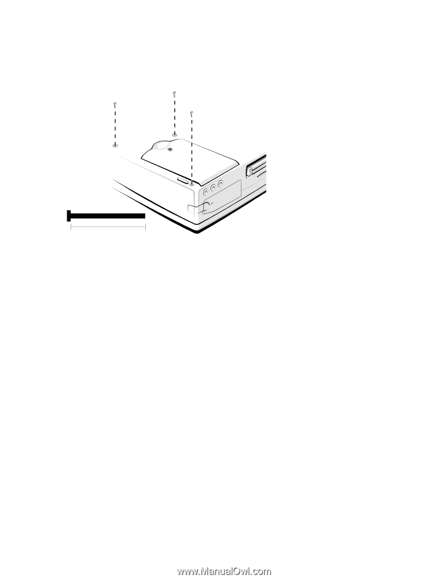
Palmrest-Assembly Retaining Screws
 |
View all Dell Latitude Xpi CD MMX manuals
Add to My Manuals
Save this manual to your list of manuals |
Page 49 highlights
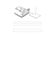
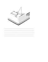
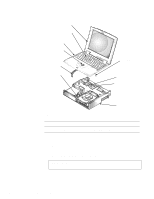
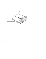
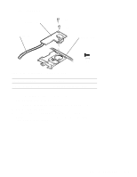
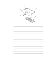
4. Close the display assembly, and turn the computer upside down on a flat work surface. 5. Remove the three palmrest-assembly retaining screws A1, A2, and A3 (see Figure 4-10). A3 (35 mm) A2 (35 mm) A1 (35 mm) 35 mm Figure 4-10. Palmrest-Assembly Retaining Screws 6. Turn the computer right-side up on the work surface, and open the display assembly. NOTE: Remember to support the display assembly with a book or similar object so that the display assembly does not open beyond 180 degrees. 7. Release the palmrest assembly from the bottom case assembly (see Figure 4-9). To release the palmrest assembly, lift the front of the assembly upward with one hand approximately 1 inch. Then, with the fingers of the other hand, disconnect the trackball cable from LIF connector JTB. 8. Rotate the front of the palmrest assembly towards the display assembly. 9. Disconnect the two keyboard cables from ZIF connectors JKB1 and JKB2. 10. Carefully lift the palmrest assembly from the bottom case assembly. The keyboard is captured in the palmrest by snaps and tabs. Removing and Replacing Parts 4-11
-
 1
1 -
2
-
3
-
4
-
5
-
6
-
7
-
8
-
9
-
10
-
11
-
12
-
13
-
14
-
15
-
16
-
17
-
18
-
19
-
20
-
21
-
22
-
23
-
24
-
25
-
26
-
27
-
28
-
29
-
30
-
31
-
32
-
33
-
34
-
35
-
36
-
37
-
38
-
39
-
40
-
41
-
42
-
43
-
 44
44 -
 45
45 -
 46
46 -
 47
47 -
 48
48 -
 49
49 -
 50
50 -
 51
51 -
 52
52 -
 53
53 -
 54
54 -
55
-
56
-
57
-
58
-
59
-
60
-
61
-
62
-
63
-
64
-
65
-
66
-
67
-
68
-
69
-
70
-
71
-
72
-
73
-
74
-
75
-
76
-
77
-
78
-
79
-
80
-
81
-
82
-
83
-
84
-
85
-
86
-
87
-
88
-
89
-
90
-
91
-
92
-
93
-
94
-
95
-
96
-
97
-
98
-
99
-
100
-
101
-
102
-
103
-
104
-
105
-
106
-
107
-
108
-
109
-
110
-
111
-
112
-
113
-
114
-
115
-
116
-
117
-
118
-
119
-
120
-
121
-
122
 |
 |