Dell M4400 Service Manual - Page 48
Replacing the DC Power Cable - graphics card
 |
View all Dell M4400 manuals
Add to My Manuals
Save this manual to your list of manuals |
Page 48 highlights
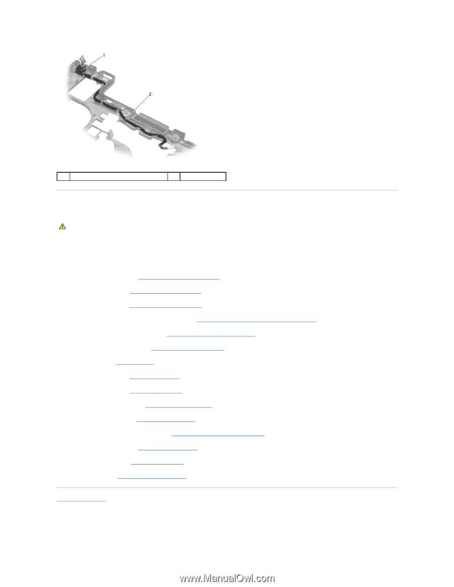
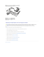
1 DC power connector 2 DC cable Replacing the DC Power Cable CAUTION: Before working inside your computer, read the safety information that shipped with your computer. For additional safety best practices information, see the Regulatory Compliance Homepage on www.dell.com at: www.dell.com/regulatory_compliance. 1. Position the DC power connector in the base assembly, aligning the guides on the connector sides with the base. 2. Route the DC power cable through the base assembly. 3. Replace the system board (see Replacing the System Board Assembly). 4. Replace the card cage (see Replacing the Express Card Cage). 5. Replace the palm rest (see Replacing the Palm Rest Assembly). 6. Replace the speaker grill and fingerprint reader cover (see Replacing the Right Speaker Grill and Fingerprint Reader). 7. Replace the discrete graphics heat sink (see Replacing the Discrete Graphics Heat Sink). 8. Replace the processor heat sink (see Replacing the Processor Heat Sink). 9. Replace the fan (see Replacing the Fan). 10. Replace the keyboard (see Replacing the Keyboard). 11. Replace the LED cover (see Replacing the LED Cover). 12. Replace the display assembly (see Replacing the Display Assembly). 13. Replace the hinge covers (see Replacing the Hinge Covers). 14. Replace the bottom of the base assembly (see Replacing the Bottom of the Base Assembly). 15. Replace the modular drive (see Replacing the Modular Drive). 16. Replace the hard drive (see Replacing the Hard Drive). 17. Follow the procedure After Working on Your Computer. Back to Contents Page
-
 1
1 -
2
-
3
-
4
-
5
-
6
-
7
-
8
-
9
-
10
-
11
-
12
-
13
-
14
-
15
-
16
-
17
-
18
-
19
-
20
-
21
-
22
-
23
-
24
-
25
-
26
-
27
-
28
-
29
-
30
-
31
-
32
-
33
-
34
-
35
-
36
-
37
-
38
-
39
-
40
-
41
-
42
-
 43
43 -
 44
44 -
 45
45 -
 46
46 -
 47
47 -
 48
48 -
 49
49 -
 50
50 -
 51
51 -
 52
52 -
 53
53 -
54
-
55
-
56
-
57
-
58
-
59
-
60
-
61
-
62
-
63
-
64
-
65
-
66
-
67
-
68
-
69
-
70
-
71
-
72
 |
 |