Dell OptiPlex 3020M Dell OptiPlex 3020M Owners Manual - Page 33
Removing the System Board, SATA HDD connector
 |
View all Dell OptiPlex 3020M manuals
Add to My Manuals
Save this manual to your list of manuals |
Page 33 highlights
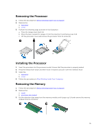
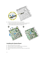
1. processor socket 2. processor fan connector 3. speaker connector 4. memory connectors ( SODIMM sockets) 5. WLAN connector 6. SATA HDD connector 7. coin-cell battery 8. PS2 and serial connector Removing the System Board 1. Follow the procedures in Before Working Inside Your Computer. 2. Remove the: a. cover b. processor fan module c. hard drive d. heatsink e. memory f. processor g. PS2 or serial connector board h. WLAN card i. coin-cell battery 3. Perform the following steps as shown in the illustration. a. Remove the screws that secure the hard-drive holder to the system board [1]. b. Lift the hard drive holder away from the system board [2]. 33
-
 1
1 -
2
-
3
-
4
-
5
-
6
-
7
-
8
-
9
-
10
-
11
-
12
-
13
-
14
-
15
-
16
-
17
-
18
-
19
-
20
-
21
-
22
-
23
-
24
-
25
-
26
-
27
-
 28
28 -
 29
29 -
 30
30 -
 31
31 -
 32
32 -
 33
33 -
 34
34 -
 35
35 -
 36
36 -
 37
37 -
 38
38 -
39
-
40
-
41
-
42
-
43
-
44
-
45
-
46
-
47
-
48
-
49
-
50
-
51
-
52
-
53
 |
 |
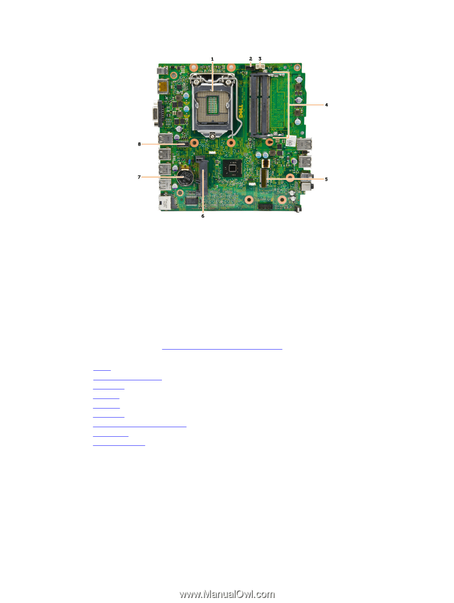
1.
processor socket
2.
processor fan connector
3.
speaker connector
4.
memory connectors ( SODIMM sockets)
5.
WLAN connector
6.
SATA HDD connector
7.
coin-cell battery
8.
PS2 and serial connector
Removing the System Board
1.
Follow the procedures in
Before Working Inside Your Computer
.
2.
Remove the:
a.
cover
b.
processor fan module
c.
hard drive
d.
heatsink
e.
memory
f.
processor
g.
PS2 or serial connector board
h.
WLAN card
i.
coin-cell battery
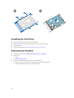
3.
Perform the following steps as shown in the illustration.
a.
Remove the screws that secure the hard-drive holder to the system board [1].
b.
Lift the hard drive holder away from the system board [2].
33