Dell OptiPlex 330 User's Guide - Page 202
Connect any cables disconnected before removing the heat sink assembly.
 |
View all Dell OptiPlex 330 manuals
Add to My Manuals
Save this manual to your list of manuals |
Page 202 highlights
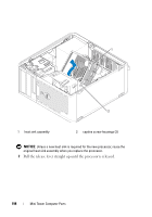
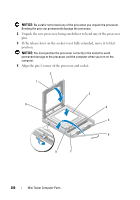
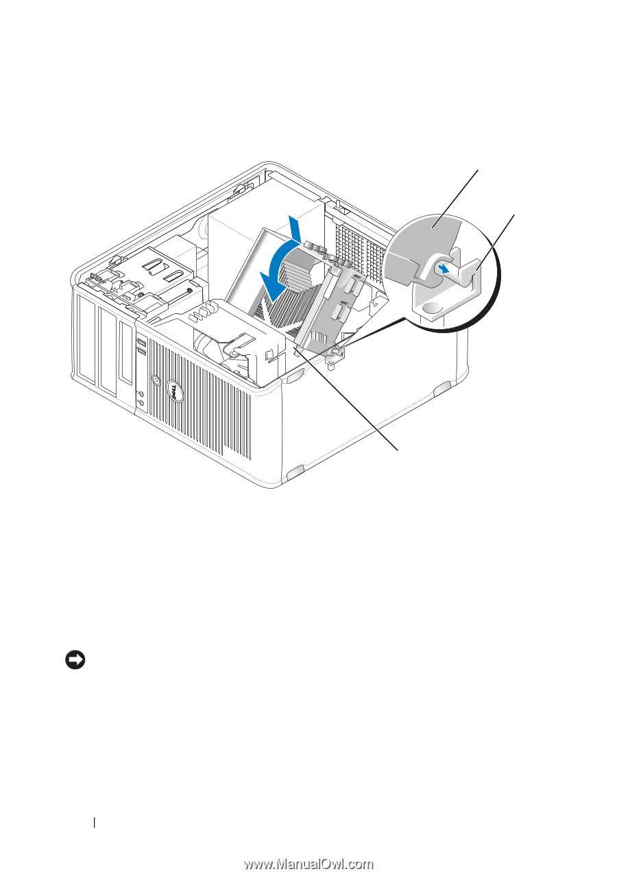
1 2 3 1 heat sink assembly 3 captive screw housing (2) 2 heat-sink assembly bracket 10 Connect any cables disconnected before removing the heat sink assembly. 11 Replace the computer cover (see "Replacing the Computer Cover" on page 207). NOTICE: To connect a network cable, first plug the cable into the network device and then plug it into the computer. 12 Connect your computer and devices to an electrical outlet, and turn them on. 13 Verify that the computer works correctly by running the Dell Diagnostics (see "Dell Diagnostics" on page 111). 202 Mini Tower Computer Parts
-
 1
1 -
2
-
3
-
4
-
5
-
6
-
7
-
8
-
9
-
10
-
11
-
12
-
13
-
14
-
15
-
16
-
17
-
18
-
19
-
20
-
21
-
22
-
23
-
24
-
25
-
26
-
27
-
28
-
29
-
30
-
31
-
32
-
33
-
34
-
35
-
36
-
37
-
38
-
39
-
40
-
41
-
42
-
43
-
44
-
45
-
46
-
47
-
48
-
49
-
50
-
51
-
52
-
53
-
54
-
55
-
56
-
57
-
58
-
59
-
60
-
61
-
62
-
63
-
64
-
65
-
66
-
67
-
68
-
69
-
70
-
71
-
72
-
73
-
74
-
75
-
76
-
77
-
78
-
79
-
80
-
81
-
82
-
83
-
84
-
85
-
86
-
87
-
88
-
89
-
90
-
91
-
92
-
93
-
94
-
95
-
96
-
97
-
98
-
99
-
100
-
101
-
102
-
103
-
104
-
105
-
106
-
107
-
108
-
109
-
110
-
111
-
112
-
113
-
114
-
115
-
116
-
117
-
118
-
119
-
120
-
121
-
122
-
123
-
124
-
125
-
126
-
127
-
128
-
129
-
130
-
131
-
132
-
133
-
134
-
135
-
136
-
137
-
138
-
139
-
140
-
141
-
142
-
143
-
144
-
145
-
146
-
147
-
148
-
149
-
150
-
151
-
152
-
153
-
154
-
155
-
156
-
157
-
158
-
159
-
160
-
161
-
162
-
163
-
164
-
165
-
166
-
167
-
168
-
169
-
170
-
171
-
172
-
173
-
174
-
175
-
176
-
177
-
178
-
179
-
180
-
181
-
182
-
183
-
184
-
185
-
186
-
187
-
188
-
189
-
190
-
191
-
192
-
193
-
194
-
195
-
196
-
 197
197 -
 198
198 -
 199
199 -
 200
200 -
 201
201 -
 202
202 -
 203
203 -
 204
204 -
 205
205 -
 206
206 -
 207
207 -
208
-
209
-
210
-
211
-
212
-
213
-
214
-
215
-
216
-
217
-
218
-
219
-
220
-
221
-
222
-
223
-
224
-
225
-
226
-
227
-
228
-
229
-
230
-
231
-
232
-
233
-
234
-
235
-
236
-
237
-
238
-
239
-
240
-
241
-
242
-
243
-
244
-
245
-
246
-
247
-
248
-
249
-
250
-
251
-
252
-
253
-
254
-
255
-
256
-
257
-
258
-
259
-
260
-
261
-
262
-
263
-
264
-
265
-
266
-
267
-
268
-
269
-
270
-
271
-
272
-
273
-
274
-
275
-
276
-
277
-
278
-
279
-
280
-
281
-
282
-
283
-
284
-
285
-
286
 |
 |
202
Mini Tower Computer Parts
10
Connect any cables disconnected before removing the heat sink assembly.
11
Replace the computer cover (see "Replacing the Computer Cover" on
page 207).
NOTICE:
To connect a network cable, first plug the cable into the network device
and then plug it into the computer.
12
Connect your computer and devices to an electrical outlet, and turn
them on.
13
Verify that the computer works correctly by running the Dell Diagnostics
(see "Dell Diagnostics" on page 111).
1
heat sink assembly
2
heat-sink assembly bracket
3
captive screw housing (2)
3
1
2