Dell OptiPlex 330 User's Guide - Page 251
Ensure that the tab on the processor cover is positioned underneath
 |
View all Dell OptiPlex 330 manuals
Add to My Manuals
Save this manual to your list of manuals |
Page 251 highlights
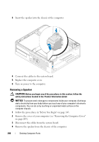
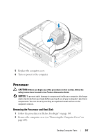
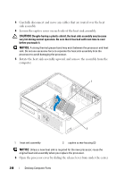
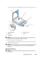
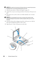
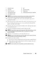
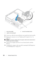
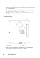
1 processor cover 3 processor 5 center cover latch 7 front alignment-notch 9 rear alignment-notch 2 tab 4 processor socket 6 release lever 8 socket and processor pin-1 indicator NOTICE: To avoid damage, ensure that the processor aligns properly with the socket, and do not use excessive force when you install the processor. 6 Set the processor lightly in the socket and ensure that the processor is positioned correctly. 7 When the processor is fully seated in the socket, close the processor cover. Ensure that the tab on the processor cover is positioned underneath the center cover latch on the socket. 8 Pivot the socket release lever back toward the socket, and snap it into place to secure the processor. 9 Clean the thermal grease from the bottom of the heat sink. NOTICE: Ensure that you apply new thermal grease. New thermal grease is critical for ensuring adequate thermal bonding, which is a requirement for optimal processor operation. 10 Apply the new thermal grease to the top of the processor. NOTICE: Ensure that the floppy drive and audio cables are not routed so that they are pinched when the heat sink assembly is installed. 11 Install the heat sink assembly: a Place the heat sink assembly back onto the heat-sink assembly bracket. b Rotate the heat sink assembly down towards the computer base and tighten the two captive screws. NOTICE: Ensure that the heat sink assembly is correctly seated and secure. Desktop Computer Parts 251
-
 1
1 -
2
-
3
-
4
-
5
-
6
-
7
-
8
-
9
-
10
-
11
-
12
-
13
-
14
-
15
-
16
-
17
-
18
-
19
-
20
-
21
-
22
-
23
-
24
-
25
-
26
-
27
-
28
-
29
-
30
-
31
-
32
-
33
-
34
-
35
-
36
-
37
-
38
-
39
-
40
-
41
-
42
-
43
-
44
-
45
-
46
-
47
-
48
-
49
-
50
-
51
-
52
-
53
-
54
-
55
-
56
-
57
-
58
-
59
-
60
-
61
-
62
-
63
-
64
-
65
-
66
-
67
-
68
-
69
-
70
-
71
-
72
-
73
-
74
-
75
-
76
-
77
-
78
-
79
-
80
-
81
-
82
-
83
-
84
-
85
-
86
-
87
-
88
-
89
-
90
-
91
-
92
-
93
-
94
-
95
-
96
-
97
-
98
-
99
-
100
-
101
-
102
-
103
-
104
-
105
-
106
-
107
-
108
-
109
-
110
-
111
-
112
-
113
-
114
-
115
-
116
-
117
-
118
-
119
-
120
-
121
-
122
-
123
-
124
-
125
-
126
-
127
-
128
-
129
-
130
-
131
-
132
-
133
-
134
-
135
-
136
-
137
-
138
-
139
-
140
-
141
-
142
-
143
-
144
-
145
-
146
-
147
-
148
-
149
-
150
-
151
-
152
-
153
-
154
-
155
-
156
-
157
-
158
-
159
-
160
-
161
-
162
-
163
-
164
-
165
-
166
-
167
-
168
-
169
-
170
-
171
-
172
-
173
-
174
-
175
-
176
-
177
-
178
-
179
-
180
-
181
-
182
-
183
-
184
-
185
-
186
-
187
-
188
-
189
-
190
-
191
-
192
-
193
-
194
-
195
-
196
-
197
-
198
-
199
-
200
-
201
-
202
-
203
-
204
-
205
-
206
-
207
-
208
-
209
-
210
-
211
-
212
-
213
-
214
-
215
-
216
-
217
-
218
-
219
-
220
-
221
-
222
-
223
-
224
-
225
-
226
-
227
-
228
-
229
-
230
-
231
-
232
-
233
-
234
-
235
-
236
-
237
-
238
-
239
-
240
-
241
-
242
-
243
-
244
-
245
-
 246
246 -
 247
247 -
 248
248 -
 249
249 -
 250
250 -
 251
251 -
 252
252 -
 253
253 -
 254
254 -
 255
255 -
 256
256 -
257
-
258
-
259
-
260
-
261
-
262
-
263
-
264
-
265
-
266
-
267
-
268
-
269
-
270
-
271
-
272
-
273
-
274
-
275
-
276
-
277
-
278
-
279
-
280
-
281
-
282
-
283
-
284
-
285
-
286
 |
 |