Dell OptiPlex 755 User's Guide - Page 24
NOTICE, User's Guide - diagnostic lights
 |
View all Dell OptiPlex 755 manuals
Add to My Manuals
Save this manual to your list of manuals |
Page 24 highlights
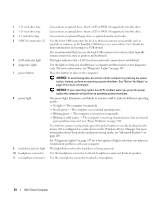
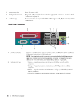
1 5.25-inch drive bay 2 5.25-inch drive bay 3 3.5-inch drive bay 4 USB 2.0 connectors (2) 5 LAN indicator light 6 diagnostic lights 7 power button 8 power light 9 hard drive activity light 10 headphone connector 11 microphone connector Can contain an optical drive. Insert a CD or DVD (if supported) into this drive. Can contain an optical drive. Insert a CD or DVD (if supported) into this drive. Can contain an optional floppy drive or optional media card reader. Use the front USB connectors for devices that you connect occasionally, such as joysticks or cameras, or for bootable USB devices (see your online User's Guide for more information on booting to a USB device). It is recommended that you use the back USB connectors for devices that typically remain connected, such as printers and keyboards. This light indicates that a LAN (local area network) connection is established. Use the lights to help you troubleshoot a computer problem based on the diagnostic code. For more information, see "Diagnostic Lights" on page 347. Press this button to turn on the computer. NOTICE: To avoid losing data, do not turn off the computer by pressing the power button. Instead, perform an operating system shutdown. See "Before You Begin" on page 21 for more information. NOTICE: If your operating system has ACPI enabled, when you press the power button the computer will perform an operating system shutdown. The power light illuminates and blinks or remains solid to indicate different operating modes: • No light - The computer is turned off. • Steady green - The computer is in a normal operating state. • Blinking green - The computer is in a power-saving mode. • Blinking or solid amber - The computer is receiving electrical power, but an internal power problem may exist (see "Power Problems" on page 339). To exit from a power-saving mode, press the power button or use the keyboard or the mouse if it is configured as a wake device in the Windows Device Manager. For more information about sleep modes and power-saving mode, see "Advanced Features" on page 269. See "Diagnostic Lights" on page 347 for a description of light codes that can help you troubleshoot problems with your computer. This light flickers when the hard drive is being accessed. Use the headphone connector to attach headphones and most kinds of speakers. Use the microphone connector to attach a microphone. 24 Mini Tower Computer
-
 1
1 -
2
-
3
-
4
-
5
-
6
-
7
-
8
-
9
-
10
-
11
-
12
-
13
-
14
-
15
-
16
-
17
-
18
-
 19
19 -
 20
20 -
 21
21 -
 22
22 -
 23
23 -
 24
24 -
 25
25 -
 26
26 -
 27
27 -
 28
28 -
 29
29 -
30
-
31
-
32
-
33
-
34
-
35
-
36
-
37
-
38
-
39
-
40
-
41
-
42
-
43
-
44
-
45
-
46
-
47
-
48
-
49
-
50
-
51
-
52
-
53
-
54
-
55
-
56
-
57
-
58
-
59
-
60
-
61
-
62
-
63
-
64
-
65
-
66
-
67
-
68
-
69
-
70
-
71
-
72
-
73
-
74
-
75
-
76
-
77
-
78
-
79
-
80
-
81
-
82
-
83
-
84
-
85
-
86
-
87
-
88
-
89
-
90
-
91
-
92
-
93
-
94
-
95
-
96
-
97
-
98
-
99
-
100
-
101
-
102
-
103
-
104
-
105
-
106
-
107
-
108
-
109
-
110
-
111
-
112
-
113
-
114
-
115
-
116
-
117
-
118
-
119
-
120
-
121
-
122
-
123
-
124
-
125
-
126
-
127
-
128
-
129
-
130
-
131
-
132
-
133
-
134
-
135
-
136
-
137
-
138
-
139
-
140
-
141
-
142
-
143
-
144
-
145
-
146
-
147
-
148
-
149
-
150
-
151
-
152
-
153
-
154
-
155
-
156
-
157
-
158
-
159
-
160
-
161
-
162
-
163
-
164
-
165
-
166
-
167
-
168
-
169
-
170
-
171
-
172
-
173
-
174
-
175
-
176
-
177
-
178
-
179
-
180
-
181
-
182
-
183
-
184
-
185
-
186
-
187
-
188
-
189
-
190
-
191
-
192
-
193
-
194
-
195
-
196
-
197
-
198
-
199
-
200
-
201
-
202
-
203
-
204
-
205
-
206
-
207
-
208
-
209
-
210
-
211
-
212
-
213
-
214
-
215
-
216
-
217
-
218
-
219
-
220
-
221
-
222
-
223
-
224
-
225
-
226
-
227
-
228
-
229
-
230
-
231
-
232
-
233
-
234
-
235
-
236
-
237
-
238
-
239
-
240
-
241
-
242
-
243
-
244
-
245
-
246
-
247
-
248
-
249
-
250
-
251
-
252
-
253
-
254
-
255
-
256
-
257
-
258
-
259
-
260
-
261
-
262
-
263
-
264
-
265
-
266
-
267
-
268
-
269
-
270
-
271
-
272
-
273
-
274
-
275
-
276
-
277
-
278
-
279
-
280
-
281
-
282
-
283
-
284
-
285
-
286
-
287
-
288
-
289
-
290
-
291
-
292
-
293
-
294
-
295
-
296
-
297
-
298
-
299
-
300
-
301
-
302
-
303
-
304
-
305
-
306
-
307
-
308
-
309
-
310
-
311
-
312
-
313
-
314
-
315
-
316
-
317
-
318
-
319
-
320
-
321
-
322
-
323
-
324
-
325
-
326
-
327
-
328
-
329
-
330
-
331
-
332
-
333
-
334
-
335
-
336
-
337
-
338
-
339
-
340
-
341
-
342
-
343
-
344
-
345
-
346
-
347
-
348
-
349
-
350
-
351
-
352
-
353
-
354
-
355
-
356
-
357
-
358
-
359
-
360
-
361
-
362
-
363
-
364
-
365
-
366
-
367
-
368
-
369
-
370
-
371
-
372
-
373
-
374
-
375
-
376
-
377
-
378
-
379
-
380
-
381
-
382
-
383
-
384
-
385
-
386
 |
 |