Dell OptiPlex Gn Reference and Installation Guide (.pdf) - Page 82
Removing the 3.5-Inch Diskette, Drive/Bracket Assembly, Removing the 5.25-
 |
View all Dell OptiPlex Gn manuals
Add to My Manuals
Save this manual to your list of manuals |
Page 82 highlights
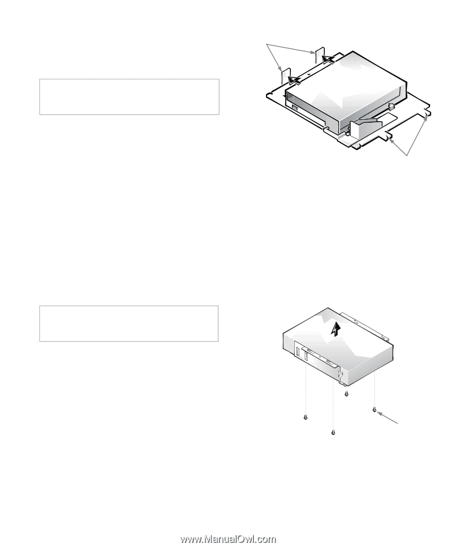
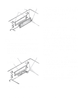
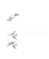
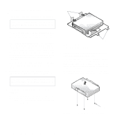
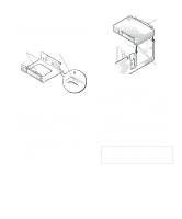
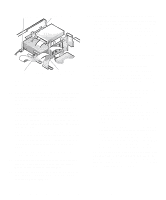
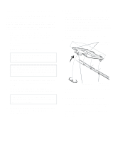
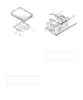
To install a drive in a 5.25-inch drive bay, follow these steps: 1. Unpack the drive and prepare it for installation. CAUTION: Ground yourself by touching an unpainted metal surface on the back of the computer. Check the documentation that accompanied the drive to verify that the drive is configured for your computer system. Change any settings necessary for your configuration. NOTE: If you are installing a non-EIDE tape drive, check the documentation for the drive to determine the jumper or switch settings used to designate the drive as drive address DS4 (not DS2 or DS3 as may be indicated in the drive documentation). Unless the drive is already set to drive 4, reconfigure its jumper or switch setting (see "Jumpers" and "Switches" in Chapter 5). If you are installing an EIDE CD-ROM or EIDE tape drive, configure the drive for the Cable Select setting. 2. Remove the computer cover as instructed in "Removing the Computer Cover" in Chapter 5. CAUTION: See "Protecting Against Electrostatic Discharge" in the safety instructions at the front of this guide. 3. Remove the 3.5-inch diskette drive/bracket assembly. Press outward on the two tabs on the left side of the drive bay to disengage the bracket from the chassis (see Figure 7-6). Then rotate the bracket upward, and remove it from the chassis. tabs notches Figure 7-6. Removing the 3.5-Inch Diskette Drive/Bracket Assembly 4. Lift the 5.25-inch drive bracket straight up and out of the chassis (see Figure 7-7). If you are replacing a drive that is already installed in the bay, be sure to disconnect the DC power cable and interface cable from the back of the drive before removing the drive/bracket assembly. To remove the old drive from the bracket, turn over the drive/ bracket assembly and unscrew the four screws that secure the drive to the bracket (shown in Figure 7-7). screws (4) Figure 7-7. Removing the 5.25-Inch Drive Bracket 7-4 Dell OptiPlex Gn and Gn+ Low-Profile Systems Reference and Installation Guide
-
 1
1 -
2
-
3
-
4
-
5
-
6
-
7
-
8
-
9
-
10
-
11
-
12
-
13
-
14
-
15
-
16
-
17
-
18
-
19
-
20
-
21
-
22
-
23
-
24
-
25
-
26
-
27
-
28
-
29
-
30
-
31
-
32
-
33
-
34
-
35
-
36
-
37
-
38
-
39
-
40
-
41
-
42
-
43
-
44
-
45
-
46
-
47
-
48
-
49
-
50
-
51
-
52
-
53
-
54
-
55
-
56
-
57
-
58
-
59
-
60
-
61
-
62
-
63
-
64
-
65
-
66
-
67
-
68
-
69
-
70
-
71
-
72
-
73
-
74
-
75
-
76
-
 77
77 -
 78
78 -
 79
79 -
 80
80 -
 81
81 -
 82
82 -
 83
83 -
 84
84 -
 85
85 -
 86
86 -
 87
87 -
88
-
89
-
90
-
91
-
92
-
93
-
94
-
95
-
96
-
97
-
98
-
99
-
100
-
101
-
102
-
103
-
104
-
105
-
106
-
107
-
108
-
109
-
110
-
111
-
112
-
113
-
114
-
115
-
116
-
117
-
118
-
119
-
120
-
121
-
122
-
123
-
124
-
125
-
126
 |
 |