Dell PowerConnect 2808 User's Guide
Dell PowerConnect 2808 Manual
 |
View all Dell PowerConnect 2808 manuals
Add to My Manuals
Save this manual to your list of manuals |
Dell PowerConnect 2808 manual content summary:
- Dell PowerConnect 2808 | User's Guide - Page 1
Dell™ PowerConnect™ 28xx Systems User Guide www.dell.com | support.dell.com - Dell PowerConnect 2808 | User's Guide - Page 2
you how to avoid the problem. CAUTION: A CAUTION indicates Dell Inc. is strictly forbidden. Trademarks used in this text: Dell, Dell OpenManage, the DELL logo, Inspiron, Dell Precision, Dimension, OptiPlex, PowerConnect refer to either the entities claiming the marks and names or their products. Dell - Dell PowerConnect 2808 | User's Guide - Page 3
17 Switch Port Configurations 17 PowerConnect 28xx Front and Back Panel Port Description 17 Physical Dimensions 21 LED Definitions 21 Power LED 22 Managed Mode LED 22 Fan LED (2824/2848 only 22 Port LEDs 22 Managed Mode Button 23 Switch Ventilation Fan 23 Cables, Port Connections, and - Dell PowerConnect 2808 | User's Guide - Page 4
, Cables, and Pinout Information 35 RJ-45 Connections for 10/100/1000BaseT Ports 35 Port Default Settings 36 Auto-Negotiation 36 MDI/MDIX 36 Flow Control 36 Back Pressure 36 Switching Port Default Settings 37 4 Starting and Configuring the Device 39 Booting the Device - Managed Mode 40 - Dell PowerConnect 2808 | User's Guide - Page 5
FLASH File 46 Erasing the Device Configuration 47 Password Recovery 47 Software Download Through TFTP Server 47 Management Modes 49 Default Values 49 Transitioning Between Modes 50 Returning to Managed Mode 51 5 Using Dell OpenManage Switch Administrator 53 Understanding the Interface 53 - Dell PowerConnect 2808 | User's Guide - Page 6
Pool 85 Excluding Addresses 87 Manually Allocating IP Addresses (Static Hosts 89 Configuring Address Binding 92 Defining Advanced Settings 93 Configuring General Device Parameters 93 7 Configuring Device Switching 95 Configuring Network Security 95 Configuring Port Based Authentication 96 - Dell PowerConnect 2808 | User's Guide - Page 7
Rapid Spanning Tree 124 Configuring VLANs 126 Defining VLAN Members 126 VLAN Port Membership Table 128 Defining VLAN Ports Settings 130 Defining VLAN LAG Settings 131 Aggregating Ports 133 Defining LAG Membership 134 Multicast Forwarding Support 134 Defining Multicast Global Parameters - Dell PowerConnect 2808 | User's Guide - Page 8
debug-mode 162 Command: do 163 Command: end 163 Command: exit (configuration 163 Command: exit (EXEC 164 Command: help 164 Command: interface ethernet 165 Command: interface port-channel 165 Command: interface vlan 166 Command: ip address 166 Command: ip default-gateway 167 Command: login - Dell PowerConnect 2808 | User's Guide - Page 9
Introduction This User's Guide contains the information needed for installing, configuring and maintaining the PowerConnect 2808, PowerConnect 2816, PowerConnect 2824, and PowerConnect 2848 Webmanaged Gigabit Ethernet switches. The PowerConnect 28xx switches can be used to connect workstations and - Dell PowerConnect 2808 | User's Guide - Page 10
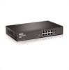
2848 The following figure illustrates the PowerConnect 2848 front panel. Figure 1-4. PowerConnect 2848 Front Panel The PowerConnect 2848 supports the following ports: • 48 Gigabit Ethernet copper ports • 4 SFP combo ports (1000BASE-SX or 1000BASE-LX) 10 Dell PowerConnect 28xx Systems User Guide - Dell PowerConnect 2808 | User's Guide - Page 11
Pressure Support On half-duplex links, the receiving port prevents buffer overflows by occupying the link so that it is unavailable for additional incoming traffic. The user may enable or disable this feature on a per-port basis. The default status on all ports is set to OFF. Dell PowerConnect 28xx - Dell PowerConnect 2808 | User's Guide - Page 12
overhead. Jumbo frames are used for server-to-server transfers. AutoMDI/MDIX Support The switch automatically detects whether the cable connected to an RJ-45 port is crossed or straight through. Standard wiring for end stations is Media-Dependent Interface (MDI) and the standard wiring for hubs - Dell PowerConnect 2808 | User's Guide - Page 13
Mode, the switch performs classic bridging. Frames are forwarded based on their destination MAC address only, regardless of the VLAN tag. MAC Multicast Support Multicast service is a limited broadcast service, which allows one-to-many and many-to-many connections for information distribution. Layer - Dell PowerConnect 2808 | User's Guide - Page 14
attributes can be grouped in the same VLAN. Port Based Virtual LANs (VLANs) Port-based VLANs classify incoming packets to VLANs based on their ingress port. Link Aggregation The PowerConnect 28xx switches support up to six aggregated links. Each of the six aggregated links may be defined with up to - Dell PowerConnect 2808 | User's Guide - Page 15
A LAG is composed of ports with the same speed set to full-duplex operation. DHCP Server Dynamic Host Configuration Protocol is a method of managing network parameter assignment from a single DHCP server. The Dynamic Host Configuration Protocol (DHCP) automates the assignment of IP addresses, subnet - Dell PowerConnect 2808 | User's Guide - Page 16
priority queues for classifying traffic. The switches support four queues per port. A CoS is defined by the user, whereby packets are related to the same Class of Service. After a packet has been classified, it is assigned to one of the queues. The PowerConnect 28xx system can classify according to - Dell PowerConnect 2808 | User's Guide - Page 17
Configurations PowerConnect 28xx Front and Back Panel Port Description The Dell™ PowerConnect™ 28xx switches use 10/100/1000BASE-T ports on the front panel for connecting to a network. The Gigabit Ethernet ports can operate at 10, 100 or 1000 Mbps. These ports support autonegotiation, duplex mode - Dell PowerConnect 2808 | User's Guide - Page 18
is powered on or not. A Mode push-button, located on the right side on the front panel, is used to transition between management modes and to reset the device. For more information about management modes and transitioning between them, see "Management Modes" on page 49. Figure 2-4. PowerConnect 2816 - Dell PowerConnect 2808 | User's Guide - Page 19
device is powered on or not. A Mode push-button, located on the right side on the front panel is used to transition between management modes and to reset the device. For more information about management modes and transitioning between them, see "Management Modes" on page 49. Dell PowerConnect 28xx - Dell PowerConnect 2808 | User's Guide - Page 20
Managed Mode LED which indicates the Ethernet switch operational status and the management mode. The Fan LED indicates the device fan operations status, and the Power LED on the front panel indicates whether the device is powered on or not. A Mode push- 20 Dell PowerConnect 28xx Systems User Guide - Dell PowerConnect 2808 | User's Guide - Page 21
in.) • Width - 440 mm (17.32 in) • Depth - 255 mm (10.04 in.) LED Definitions The front panel contains LEDs that indicate the status of links, power supply, fan status, and Managed Mode status. Dell PowerConnect 28xx Systems User Guide 21 - Dell PowerConnect 2808 | User's Guide - Page 22
more fans have failed. Port LEDs 10/100/1000BASE-T Port LEDs Each 10/100/1000BASE-T port has two LEDs. Speed/Link/Activity is indicated on the left LED and the duplex mode is indicated on the right LED. The following figure illustrates the RJ-45 10/100/1000BASE-T LEDs. 22 Dell PowerConnect 28xx - Dell PowerConnect 2808 | User's Guide - Page 23
them, see "Management Modes" on page 49. Switch Ventilation Fan The PowerConnect 2848 switch has three fans and the PowerConnect 2824 switch has one fan for system ventilation. The PowerConnect 2808 and PowerConnect 2816 devices have no internal fans. Dell PowerConnect 28xx Systems User Guide 23 - Dell PowerConnect 2808 | User's Guide - Page 24
about cables and port connections. Copper cable diagnostics are supported. High-speed workstations, hubs, routers, or other switches are connected through standard RJ-45 connectors to the switch physical interface ports, located on the front panel. For each device, the supported mode is set to - Dell PowerConnect 2808 | User's Guide - Page 25
PowerConnect 2848 switch supports four SFP transceivers combo ports for various fiber-based modules (1000BASE-SX or 1000BASE-LX). Only one of the two physical connections of a combo port can be used at any time. The system can switch from the RJ-45 to the SFP (or vice versa) without a system reset - Dell PowerConnect 2808 | User's Guide - Page 26
The PowerConnect 28xx supports a single internal power supply to provide power for switching operations. The internal power supply supports input voltages between 100 and 240 VAC. The AC power connector is located on the back panel of the switch. 26 Dell PowerConnect 28xx Systems User Guide - Dell PowerConnect 2808 | User's Guide - Page 27
the PowerConnect Device This section contains information about device unpacking, location, installation, and cable connections. Installation Precautions CAUTION Before performing any of the following procedures, read and follow the safety instructions located in the System Information Guide - Dell PowerConnect 2808 | User's Guide - Page 28
following items are included: • The device • AC power cable • Self-adhesive rubber pads (for on-shelf installation) • Rack-mount kit for installation • Documentation CD • Product Information Guide Unpacking the Device To unpack the PowerConnect device: NOTE: Before unpacking the device, inspect the - Dell PowerConnect 2808 | User's Guide - Page 29
a rack as follows: 1 Place the supplied rack-mounting bracket on one side of the device ensuring the mounting holes on the device line up to the mounting holes on the rack mounting bracket. The following figure illustrates where to mount the brackets. Dell PowerConnect 28xx Systems User Guide 29 - Dell PowerConnect 2808 | User's Guide - Page 30
pads (provided with the device) on each marked location on the bottom of the chassis. 2 Set the device on a flat surface, while leaving 2 inches (5.08 cm) on each side and 5 inches (12.7 cm) at the back. 3 Ensure that the device has proper ventilation. 30 Dell PowerConnect 28xx Systems User Guide - Dell PowerConnect 2808 | User's Guide - Page 31
the supplied screws into the rack-mounting holes and tighten with a screwdriver. 4 Repeat the process for the wall-mounting bracket on the other side of the device. 5 Place the device on the wall in the location where the device is being installed. Dell PowerConnect 28xx Systems User Guide 31 - Dell PowerConnect 2808 | User's Guide - Page 32
with internal crossover wiring (MDI/MDIX) operation under Auto-Negotiation mode. Standard straight-through twisted-pair cables can be used to connect to any other Ethernet network (systems, servers, switches or routers) that supports auto-negotiation. 32 Dell PowerConnect 28xx Systems User Guide - Dell PowerConnect 2808 | User's Guide - Page 33
RS-232 crossover cable to the terminal running VT100 terminal emulation software. 2 Ensure that the terminal emulation software is set as follows: a Select the appropriate serial port (serial port 1 or serial port 2) to connect to the console. b Set the data rate to 9600 baud. c Set the data format - Dell PowerConnect 2808 | User's Guide - Page 34
in the steps detailed in Starting and Configuring the Device. Figure 3-4. Connecting to Power Supply 3 After connecting the device to a power source, confirm that the device is connected and operating correctly by examining the LEDs on the front panel. 34 Dell PowerConnect 28xx Systems User Guide - Dell PowerConnect 2808 | User's Guide - Page 35
Diagnostics are supported. RJ-45 Connections for 10/100/1000BaseT Ports The 10/100/1000BaseT ports are copper twisted-pair ports. To establish a link for the twisted-pair ports, Tx pair on one cable end must be connected to the Rx pair on the other cable end, and vice versa. If the cabling is done - Dell PowerConnect 2808 | User's Guide - Page 36
for end stations is known as MDI (Media Dependent Interface), and the standard wiring for hubs and switches is known as MDIX.) Flow Control The device supports 802.3x Flow Control for ports configured with the Full Duplex mode. By default, this feature is enabled. It can be enabled per port. The - Dell PowerConnect 2808 | User's Guide - Page 37
and mode Port forwarding state Port tagging Flow Control Back Pressure MDIX (not user-configurable) Default Setting 10/100/1000BaseT copper: auto-negotiation full duplex Enabled No tagging On Off (disabled on ingress) On (relevant to coppers ports only) Dell PowerConnect 28xx Systems User Guide - Dell PowerConnect 2808 | User's Guide - Page 38
38 Dell PowerConnect 28xx Systems User Guide - Dell PowerConnect 2808 | User's Guide - Page 39
a terminal connection. • A terminal connection is required if the device is to be used in a managed mode. NOTE: The PowerConnect 2808 has an internal serial port. NOTE: Before proceeding, read the release notes for this product. The release notes can be downloaded from http://support.dell.com. NOTE - Dell PowerConnect 2808 | User's Guide - Page 40
Standard Device Installation Advanced Configuration: IP Address from DHCP Advanced Device Installation Booting the Device - Managed Mode The procedure described in this section refers to the device when set to operate as a managed switch. The PowerConnect 2808/16/24/48 models include a built-in - Dell PowerConnect 2808 | User's Guide - Page 41
is to be managed (by default, every external and internal port is a member of the VLAN 1) • The IP subnet mask for the network • The default gateway (next hop router) IP address for configuring the default route. The Setup Wizard guides you through the initial device configuration, and gets the - Dell PowerConnect 2808 | User's Guide - Page 42
and SNMP Management System IP address (optional) • Username and Password • Device IP address • IP subnet mask • Default Gateway IP address The Setup Wizard displays the following information: Welcome to Dell Easy Setup Wizard. The Setup Wizard guides you through the initial switch configuration, and - Dell PowerConnect 2808 | User's Guide - Page 43
default VLAN ,(VLAN #2) . This is the IP address you use to access the Telnet, Web interface, or SNMP interface for the switch. To setup an IP address: Please enter the IP address of the device (A.B.C.D):10.6.22.100 Please enter the IP subnet mask (A.B.C.D or nn):[255.255.255.224] Dell PowerConnect - Dell PowerConnect 2808 | User's Guide - Page 44
. The following is displayed (as per the example parameters described): This is the configuration information that has been collected SNMP Interface = [email protected] User Account setup = admin Password Management IP address = 10.6.22.100 255.255.255.224 Default Gateway is 10.6.22.97 - Dell PowerConnect 2808 | User's Guide - Page 45
as a DHCP client. When the device is reset, the DHCP command is saved in the configuration file, but not the IP address. To configure the device so it will retrieve an IP address from a DHCP server, use the web interface (see "Defining DHCP Server Settings" on page 83). NOTE: It is not necessary - Dell PowerConnect 2808 | User's Guide - Page 46
: The length of time taken by the download varies according to the tool used. Erase FLASH File In some cases, the device configuration must be erased. If the configuration is erased, all parameters configured via CLI, EWS or SNMP must be reconfigured. 46 Dell PowerConnect 28xx Systems User Guide - Dell PowerConnect 2808 | User's Guide - Page 47
. To download a system image through the TFTP server: 1 Ensure that an IP address is configured on one of the device ports and pings can be sent to a TFTP server. 2 Make sure that the file to be downloaded is saved on the TFTP server (the ros file). Dell PowerConnect 28xx Systems User Guide 47 - Dell PowerConnect 2808 | User's Guide - Page 48
programming it into the flash updates the boot image. The boot image is loaded when the device is powered on. A user has no control over the boot image copies. To download a boot image through the TFTP server: 1 Ensure that an IP address is configured on one of the device ports and pings can be sent - Dell PowerConnect 2808 | User's Guide - Page 49
22). Default Values The factory default values, used when the device is in Unmanaged mode, include: • IP Address - 192.168.2.1 • Netmask - 255.255.255.0 • Username - admin • Permission - R/W privilege • DHCP Client - Off • Flow Control - On • STP - Off Dell PowerConnect 28xx Systems User Guide 49 - Dell PowerConnect 2808 | User's Guide - Page 50
Transitioning Between Modes The following diagram summarizes movement between modes: Figure 4-2. Transitioning Between Management Modes 50 Dell PowerConnect 28xx Systems User Guide - Dell PowerConnect 2808 | User's Guide - Page 51
the saved configuration. • Use Current IP/User Name/Password - When restoring local configuration, this option uses the system default IP address, user name and password. • Apply Changes - The selected configuration is restored and the device reboots. Dell PowerConnect 28xx Systems User Guide 51 - Dell PowerConnect 2808 | User's Guide - Page 52
52 Dell PowerConnect 28xx Systems User Guide - Dell PowerConnect 2808 | User's Guide - Page 53
of the home page, the device view provides a view of the device, an information or table area, and configuration instructions. Figure 5-1. Switch Administrator Components 5 Table 5-1 lists the interface components with their corresponding numbers. Dell PowerConnect 28xx Systems User Guide 53 - Dell PowerConnect 2808 | User's Guide - Page 54
device ports, current configuration and Dell Support. For more information, see "Information Buttons." Device Representation The PowerConnect home page contains a graphical device representation of the front panel. Figure 5-2. Port LED Indicators 54 Dell PowerConnect 28xx Systems User Guide - Dell PowerConnect 2808 | User's Guide - Page 55
Help About Log Out Description Opens the Dell Support page at support.dell.com. Online help containing information to assist in configuring and managing the device. The online help pages are linked directly to the page currently open. For example, if the IP Addressing page is open, the help topic - Dell PowerConnect 2808 | User's Guide - Page 56
in the CLI) in the address bar and press . For information about assigning an IP address to a device, see "Static IP Address and Subnet Mask." 3 When the Enter Network Password window opens, enter a user name and password. NOTE: The device is not configured with a default password, and can - Dell PowerConnect 2808 | User's Guide - Page 57
edit all pages of the interface. • Monitor - This is a read-only mode where you can see a subset of the interface pages, but you cannot edit them. For more information about setting the access level, see ("Defining the Local User Databases" on page 69). Dell PowerConnect 28xx Systems User Guide 57 - Dell PowerConnect 2808 | User's Guide - Page 58
58 Dell PowerConnect 28xx Systems User Guide - Dell PowerConnect 2808 | User's Guide - Page 59
security features, downloading device software, and resetting the device. To open the System page, click System in the tree view. Figure 6-1. System 6 Defining General Device Information The General page contains links to pages for configuring device parameters. Viewing Device Information - Dell PowerConnect 2808 | User's Guide - Page 60
is currently running. • MAC Address - Specifies the device MAC address. • Sys Object ID - Specifies the vendor's authoritative identification of the network management subsystem contained in the entity. • Service Tag - Specifies the service reference number used when servicing the device. • Asset - Dell PowerConnect 2808 | User's Guide - Page 61
3 Click Apply Changes. The system parameters are defined, and the device is updated. Initiating a Telnet Session: 1 Open the Asset page. 2 Click Telnet. → Versions in the tree view. Figure 6-3. Versions • Software Version - The current software version running on the device. • Boot Version - The - Dell PowerConnect 2808 | User's Guide - Page 62
a remote location. For more information about saved Configuration files, see "Managing Files" on page 80. To open the Reset page, click System → General → Reset in the tree view. Figure 6-4. Reset Resetting the Device 1 Open the Reset page 2 Click reset. A confirmation message displays. 3 Click OK - Dell PowerConnect 2808 | User's Guide - Page 63
through power cycles just like in Managed Mode. To use Secure Mode, configure the device in Managed Mode, and then switch to Secure Mode via the web interface. To exit Secure Mode, press the Managed Mode button on the device to enter the Managed Mode default configuration with the default IP address - Dell PowerConnect 2808 | User's Guide - Page 64
Parameters • DHCP - The DHCP client can be enabled to acquire the network configuration dynamically. The DHCP default value is Disable. This field enables the DHCP client. • IP Address - Specifies the static IP Address currently assigned to the device. • Subnet Mask- Specifies the subnet mask of - Dell PowerConnect 2808 | User's Guide - Page 65
to Disable. 3 Set the IP Address, Subnet Mask and Default Gateway. 4 Click Apply Changes. The static interface parameters are set and the device is updated. Running Cable Diagnostics The Diagnostics page contains links to pages for performing virtual cable tests on copper and fiber optics cables.To - Dell PowerConnect 2808 | User's Guide - Page 66
to the port. - Open Cable - The cable is connected on only one side. - Short Cable - The cable is 2 meters long. - OK - The cable passed the test. - Fiber Cable - A fiber cable is connected to the port. • Cable Fault Distance - The distance from the port where the cable error occurred. • Last Update - Dell PowerConnect 2808 | User's Guide - Page 67
only when the link is present. To open the Optical Transceiver Diagnostics page, click System→ Diagnostics→ Optical Transceiver Diagnostics in the tree view. Figure 6-8. Optical Transceiver Diagnostics • Port - The port to which the fiber cable is connected. • Temperature - The temperature - Dell PowerConnect 2808 | User's Guide - Page 68
occurred in the cable. • Data Ready - The transceiver has achieved power up and data is power up and data is ready. • N/A - Not Available, N/S - Not Supported, W - Warning, E - Error. Fiber Optic analysis feature works only on SFPs that support the digital diagnostic standard SFF-4872. 68 Update - Dell PowerConnect 2808 | User's Guide - Page 69
Security page provides access to security pages that contain fields for setting security parameters for user database, password and RADIUS security. To open the Management Security page, click System→Management Security in the tree view. Defining the Local User Databases The Local User Database - Dell PowerConnect 2808 | User's Guide - Page 70
Click Apply Changes. The user access rights and passwords are defined, and the device is updated. Defining a New User: 1 Open the the fields. 4 Click Apply Changes. The new user is defined, and the device is updated. Displaying the Local User Table: 1 Open the Local User Database page. 2 Click Show - Dell PowerConnect 2808 | User's Guide - Page 71
method for: • Telnet Access • Web Access • Console to Device Access To open the RADIUS Settings page, click System → Management Security → RADIUS in the tree view. Figure 6-12. RADIUS Settings • IP Address - The list of Authentication Server IP addresses. Update with your book title 71 - Dell PowerConnect 2808 | User's Guide - Page 72
server. This key is encrypted. • Source Address - Specifies the source IP address that is used for communication with RADIUS servers. Defining RADIUS Parameters: 1 Open the RADIUS Settings page. 2 Define the fields. 3 Click Apply Changes. The RADIUS setting are updated to the device. Adding a RADIUS - Dell PowerConnect 2808 | User's Guide - Page 73
RADIUS Server Page 3 Define the fields. 4 Click Apply Changes. The new RADIUS server is added, and the device is updated. Displaying the RADIUS Server List: 1 Open the RADIUS Settings page. 2 Click Show All. The Show all RADIUS Servers page opens: Figure 6-14. Show all RADIUS Servers Modifying the - Dell PowerConnect 2808 | User's Guide - Page 74
SNMP) provides a method for managing network devices. Devices supporting SNMP run a local software (agent). The SNMP agents maintain a list of variables, which are used to manage the device. The variables are defined in the Management Information Base (MIB). The MIB contains the variables controlled - Dell PowerConnect 2808 | User's Guide - Page 75
page. 2 Select Enable in the SNMP Notifications field. 3 Click Apply Changes. SNMP notifications are enabled, and the device is updated. Enabling Authentication Notifications 1 Open the SNMP Global Parameters page. 2 Select Enable in the Authentication Notifications field. 3 Click Apply Changes - Dell PowerConnect 2808 | User's Guide - Page 76
IP addresses. • Community String - Functions as a password and used to authenticate the selected management station to the device. • Access Mode - Defines the access rights of the community. The possible field values are: - Read Only - The management access is restricted to read-only, for all MIBs - Dell PowerConnect 2808 | User's Guide - Page 77
Station - Defines an SNMP community for a specific management station. - All - Defines an SNMP community for all management stations. 4 Define the remaining fields. 5 Click Apply Changes. The new community is saved, and the device is updated. Displaying all Communities 1 Open the SNMP Community - Dell PowerConnect 2808 | User's Guide - Page 78
the IP address to whom the traps are sent. • Community String - Functions as a password and used to authenticate the selected management station to the device. • Notification Version - Determines the trap type. The possible field values are: - SNMPv1 - SNMP Version 1 traps are sent. 78 Update with - Dell PowerConnect 2808 | User's Guide - Page 79
Recipients page opens: 3 Define the relevant fields. 4 Click Apply Changes. The notification recipient is added, and the device is updated. Displaying Notification Recipients Tables 1 Open Notification Recipients page. 2 Click Show All. The Notification Recipients Tables page opens: Figure 6-20 - Dell PowerConnect 2808 | User's Guide - Page 80
of the following configuration files: • Startup Configuration File - Contains the commands required to reconfigure the device to the same settings as when the device is powered down or rebooted. • Running Configuration File - Contains all Startup file commands, as well as all commands entered during - Dell PowerConnect 2808 | User's Guide - Page 81
file is downloaded. The possible field values are: - Software Image - Downloads the software image file. - Boot Code - Downloads the boot file. Configuration Download • Server IP Address - The Server IP Address from which the configuration files are downloaded. Update with your book title 81 - Dell PowerConnect 2808 | User's Guide - Page 82
. • Upload via HTTP - Enables initiating a configuration file upload via the FTP server. • TFTP Server IP Address - The Server IP Address to which the file is uploaded. • Destination File Name (1-64 Characters) - Indicates the file path to which the file is uploaded. 82 Update with your book title - Dell PowerConnect 2808 | User's Guide - Page 83
Settings 1 Open the Restore Defaults page. 2 Check the Restore Configuration Factory Defaults checkbox. 3 Click Apply Changes. The settings are restored. Defining DHCP Server Settings The DHCP server is used mainly for centralized control over assignment of IP addresses to attached hosts. A switch - Dell PowerConnect 2808 | User's Guide - Page 84
/connections take place, for any reason). • Dynamic allocation - A network device obtains a leased IP address for a specified period of time. The IP address is revoked at the end of this period and the switch must request another IP address. This section contains information for configuring - Dell PowerConnect 2808 | User's Guide - Page 85
Optionally specifies the number of pings that are sent before an IP address can be assigned to a requesting client. The range is 1 to 10 and the default value is two. - Use Default - Reverts to the default Ping Retries setting (2 retries). • DHCP Ping Timeout- Optionally specifies the amount of time - Dell PowerConnect 2808 | User's Guide - Page 86
network mask. • Prefix Length - Specifies the number of bits that comprise the address prefix. • Address Pool Start - Specifies the first IP address in the range of the network pool. • Address Pool End - Specifies the last IP address in the range of the network pool. • Lease Duration - Specifies the - Dell PowerConnect 2808 | User's Guide - Page 87
. These addresses are referred to as excluded addresses. A single IP address or a range of IP addresses can be excluded. The Excluded Addresses page lists the excluded addresses. To open the Excluded Addresses page, click System → DHCP Server → Excluded Addresses in the tree view. Update with your - Dell PowerConnect 2808 | User's Guide - Page 88
Figure 6-26. Excluded Addresses • Start IP Address - Displays the first IP address in the range of excluded IP addresses. • End IP Address - Displays the last IP address in the range of excluded IP addresses. Adding an Excluded Address 1 Open the Excluded Addresses page. 2 Click Add. The Add - Dell PowerConnect 2808 | User's Guide - Page 89
(Static Hosts) The Static Hosts page is used to manually allocate IP addresses to network hosts. To open the Static Hosts page, click System → DHCP Server → Static Hosts in the tree view. Figure 6-28. Static Hosts • Host Name - - Dell PowerConnect 2808 | User's Guide - Page 90
configured to use h-node, a computer always tries p-node first and uses b-node only if p-node fails. This is the default. • SNTP Server - Specifies the time server for the DHCP static host. • Next Server - Specifies the IP address Add. The Add Static Host page opens: 90 Update with your book title - Dell PowerConnect 2808 | User's Guide - Page 91
Static Host 3 Define the relevant fields. 4 Click Apply Changes. The static host is added, and the device is updated. Displaying Static Hosts Tables 1 Open the Static Hosts page. 2 Click Show All. The Static Hosts Table page opens: Figure 6-30. Static Hosts Table Update with your book title 91 - Dell PowerConnect 2808 | User's Guide - Page 92
in the network environment/connections take place, for any reason). - Dynamic allocation - A network device obtains a leased IP address for a specified period of time. The IP address is revoked at the end of this period and the switch must request another IP address. 92 Update with your book title - Dell PowerConnect 2808 | User's Guide - Page 93
. The changes to these attributes are applied only after the device is reset. To open the Advanced Settings page, click System → Advanced Settings in the tree view. Configuring General Device Parameters The General Settings page provides information for defining general device parameters.To open the - Dell PowerConnect 2808 | User's Guide - Page 94
94 Update with your book title - Dell PowerConnect 2808 | User's Guide - Page 95
Configuring Device Switching This section provides all system operation and general information for configuring network security, ports, Address tables, GARP, VLANs, Spanning Tree, Port Aggregation, and Multicast Support. Configuring system services. Port based authentication creates two access - Dell PowerConnect 2808 | User's Guide - Page 96
select Switch → Network Security. Configuring Port Based Authentication The Port Based Authentication page contains fields for configuring port based authentication and for enabling Guest VLANs. To open the Port Based Authentication page, click Switch → Network Security → Port Based Authentication - Dell PowerConnect 2808 | User's Guide - Page 97
a RADIUS server is configured, and port authentication is enabled and set to 802.1x multi-session mode. - If the Radius Accept Message doesn't contain the supplicant's VLAN, the supplicant is rejected. - Authenticated ports are added to the supplicant VLAN as untagged. Update with your book title - Dell PowerConnect 2808 | User's Guide - Page 98
- Authenticated ports remain unauthenticated VLAN and Guest VLAN members. Static VLAN configuration is not applied to the port. - The following list of VLANs cannot participate in DVA: an Unauthenticated VLAN, a Dynamic VLAN that was created by GVRP, a Voice VLAN, a Default VLAN and a Guest VLAN. - - Dell PowerConnect 2808 | User's Guide - Page 99
Table. 5 Select the Copy to check box to define the interfaces to which the Port based authentication parameters are copied. 6 Click Apply Changes. The parameters are copied to the selected port in the Port Based Authentication Table, and the device is updated. Update with your book title 99 - Dell PowerConnect 2808 | User's Guide - Page 100
source. This is the default value. - Shutdown - Discards the packet from any unlearned source and locks the port. Ports remain locked until they are activated, or the device is reset. • Traps - Enables or disables sending traps to the host if a violation occurs. 100 Update with your book title - Dell PowerConnect 2808 | User's Guide - Page 101
of packets that arrived on the interface in single-host mode, from a host whose MAC address is not the client (supplicant) MAC address. Displaying the Multiple Hosts Table 1 Open the Multiple Hosts page. 2 Click Show All. The Multiple Hosts Table opens: Figure 7-4. Multiple Hosts Table Update with - Dell PowerConnect 2808 | User's Guide - Page 102
lists. To open the Authenticated Users page, click Switch → Network Security → Authenticated Users. Figure 7-5. Authenticated Users • User Name - List of users authorized via the RADIUS Server. • Port - The port number(s) used for authentication - per user name. • Session Time - The amount of time - Dell PowerConnect 2808 | User's Guide - Page 103
Configuring Ports The Ports page contains links to port functionality pages including advanced features, such as Green Ethernet, Storm Control and Port Mirroring. To open the Ports page, click Switch → Ports. Defining Port Parameters The Port Configuration page contains fields for defining port - Dell PowerConnect 2808 | User's Guide - Page 104
detect the cable type. - MDI (Media Dependent Interface) - Used for end stations. - MDIX (Media Dependent Interface with Crossover) - Used for hubs and switches. • Current MDI/MDIX- The currently configured device MDI/MDIX settings. • LAG - Specifies if the port is part of a LAG. 104 Update with - Dell PowerConnect 2808 | User's Guide - Page 105
evenly to all servers, or redirect the packets to the next available server. Load Balancing is configured on the "LAG Configuration" on page 106 page. LAGs can be configured according to the following load balancing types: Layer 2, or Layer 2 and Layer 3 or Layer3. Update with your book title 105 - Dell PowerConnect 2808 | User's Guide - Page 106
fields for configuring parameters for configured LAGs. The device supports up to four LAGs, each having six members. For information about Link Aggregated Groups and assigning ports to LAGs, refer to Aggregating Ports. To open the LAG Configuration page, click Switch→ Ports→ LAG Configuration in the - Dell PowerConnect 2808 | User's Guide - Page 107
Auto-negotiation is a protocol between two link partners that enables a LAG to advertise its transmission rate and flow control (the flow control default is enabled) abilities to its partner. • Current Auto Negotiation - The currently configured Auto Negotiation setting. • Admin Speed - The speed at - Dell PowerConnect 2808 | User's Guide - Page 108
when the link is set to auto-selection of copper/fiber. The short-reach method is only for a link established at 1 Gigabyte, and is not compatible with Fast Ethernet. To open the Green Ethernet Configuration page, click Switch→ Ports→ Green Ethernet Configuration in the tree view. 108 Update with - Dell PowerConnect 2808 | User's Guide - Page 109
in hours. - Reset - Click to set the Cumulative Power Saved counter back to 0. • Link Down Energy Saving Mode - Indicates whether the Energy-Detect energy saving mode is on or off for the device ports. • Link Short-Reach Energy Saving Mode - Indicates whether the Short-Reach energy saving mode is on - Dell PowerConnect 2808 | User's Guide - Page 110
length can be determined on Giga ports only), or that the Port Link is down. • Cable Length - The automatically-detected length of the cable. Enabling Green Ethernet on the Device 1 Open the Green Ethernet Configuration page. 2 Enable the desired energy saving methods. 3 Click Apply Changes. Green - Dell PowerConnect 2808 | User's Guide - Page 111
Control • Port - The port from which storm control is enabled. • Broadcast Control - Enables or disables forwarding broadcast packet types on the device. • Mode - Specifies the Broadcast mode currently enabled page. 2 Click Show All. The Storm Control Table opens: Update with your book title 111 - Dell PowerConnect 2808 | User's Guide - Page 112
to ports configured to be destination ports: • Ports cannot be configured as a source port. • Ports cannot be a LAG member. • IP interfaces are not configured on the port. • GVRP is not enabled on the port. • The port is not a VLAN member. • Only one destination port can be defined. 112 Update - Dell PowerConnect 2808 | User's Guide - Page 113
ports configured to be source ports: • Source Ports cannot be a LAG member. • Ports cannot be configured as a destination port. • All packets are transmitted tagged from the destination port. • Monitored all RX/TX packets to the same port. To open the Port Mirroring page, click Switch→ Ports→ Port - Dell PowerConnect 2808 | User's Guide - Page 114
, and the device is updated. Configuring Address Tables MAC addresses are stored in the Dynamic Address database. A packet addressed to a destination stored in the database is forwarded immediately to the port. The Dynamic Address Table can be sorted by interface, VLAN, and interface type. MAC - Dell PowerConnect 2808 | User's Guide - Page 115
. The default value is 300 seconds. • Interface - Specifies the interface for which the table is queried. There are two interface types from which to select. - Port - Specifies the port numbers for which the table is queried. - LAG - Specifies the LAG for which the table is queried. • MAC Address - Dell PowerConnect 2808 | User's Guide - Page 116
Tree in the tree view. Defining STP Global Settings The STP Global Settings page contains parameters for enabling and configuring STP operation on the device. To open the STP Global Settings page, click Switch→ Spanning Tree → Global Settings in the tree view. 116 Update with your book title - Dell PowerConnect 2808 | User's Guide - Page 117
mode by which STP is enabled on the device. The possible field values are: - Classic STP - Enables Classic STP on the device. This is the default value. - Rapid STP - Enables Rapid STP on the device. • BPDU Handling - Determines how BPDU packets are managed when STP is disabled on the port/ device - Dell PowerConnect 2808 | User's Guide - Page 118
remains in a listening and learning state before forwarding packets. The default is 15 seconds. • Bridge ID - Identifies the Bridge priority and MAC address. • Root Bridge ID - Identifies the Root Bridge priority and MAC address. • Root Port - The port number that offers the lowest cost path from - Dell PowerConnect 2808 | User's Guide - Page 119
the STP Port Settings page, click Switch→ Spanning Tree→ Port Settings in the tree view. Figure 7-17. STP Port Settings • Select a Port - Port on which STP is enabled. • STP - Enables or disables STP on the port. • Fast Link - When selected, enables Fast Link mode for the port. If Fast Link mode is - Dell PowerConnect 2808 | User's Guide - Page 120
mode. The port can forward traffic and learn new MAC addresses. • Role - Displays the port role assigned by the STP algorithm to provide to STP paths. The possible field values are: - Root - Provides the lowest cost path to forward packets to the root switch. - Designated - Indicates the port or LAG - Dell PowerConnect 2808 | User's Guide - Page 121
has changed from the Blocking state to the Forwarding state. • LAG - The LAG to which the port is attached. Enabling STP on a Port 1 Open the STP Port Settings page. 2 Select Enabled in the STP Port Status field. 3 Define the Fast Link, Path Cost, and the Priority fields. 4 Click Apply Changes. STP - Dell PowerConnect 2808 | User's Guide - Page 122
Switch→ Spanning Tree→ LAG Settings in the tree view. Figure 7-18. STP LAG Settings • Select a LAG - The user-defined LAG. For more information, see "Defining LAG Membership" on page 134. • STP - Enables or disables STP on the LAG. • Fast Link - Enables Fast Link mode for the LAG. If Fast Link mode - Dell PowerConnect 2808 | User's Guide - Page 123
leaves. Backup ports occur only when two ports are connected in a loop by a point-to-point link, or when a LAN has two or more connections connected to a shared segment. - Disabled - The port is not participating in the Spanning Tree. • Path Cost (1-200000000) - Amount the LAG contributes to the - Dell PowerConnect 2808 | User's Guide - Page 124
Parameters 1 Open the STP LAG Settings page. 2 Select a LAG from the Select a LAG drop-down menu. 3 Modify the fields as desired. 4 Click Apply Changes. The STP LAG parameters are modified, and the device is updated. Configuring Rapid Spanning Tree While Classic Spanning Tree guarantees preventing - Dell PowerConnect 2808 | User's Guide - Page 125
leaves. Backup ports occur only when two ports are connected in a loop. Backup ports also occur when a LAN has two or more connections connected to a shared segment. - Disabled - The port is not participating in the Spanning Tree (the port's link is down). • Mode - Displays the STP mode by which - Dell PowerConnect 2808 | User's Guide - Page 126
device supports 64 VLANs. All ports must have a defined PVID. If no other value is configured the default VLAN PVID is used. VLAN number 1 is the default VLAN, and cannot be deleted from the system. To open the VLAN Membership page, click Switch→ VLAN→ VLAN Membership in the tree view. 126 Update - Dell PowerConnect 2808 | User's Guide - Page 127
name. • Unauthorized Users - Enables or disables unauthorized users from accessing a VLAN. • Remove VLAN - When selected, removes the VLAN from the VLAN Membership Table. Adding New VLANs 1 Open the VLAN Membership page. 2 Click Add. The Create New VLAN page opens. Update with your book title 127 - Dell PowerConnect 2808 | User's Guide - Page 128
through the Port Control settings. Ports can have the following values: Table 7-1. VLAN Port Membership Table Port Control T Definition The interface is a member of a VLAN. All packets forwarded by the interface are tagged. The packets contain VLAN information. 128 Update with your book - Dell PowerConnect 2808 | User's Guide - Page 129
interface is not a VLAN member. Packets associated with the interface are not forwarded. The VLAN Port Membership Table displays the ports and the ports states, as well as LAGs. Ports which are LAG members are not displayed in the VLAN Port Membership Table. Assigning Ports to a VLAN Group 1 Open - Dell PowerConnect 2808 | User's Guide - Page 130
a VLAN. The port default VLAN ID (PVID) is configured on the VLAN Port Settings page. All untagged packets arriving to the device are tagged by the ports PVID. To open the VLAN Port Settings page, click Switch→ VLAN→ Port Settings in the tree view. Figure 7-22. VLAN Port Settings • Port - The port - Dell PowerConnect 2808 | User's Guide - Page 131
for managing LAGs that are part of a VLAN. VLANs can either be composed of individual ports or of LAGs. Untagged packets entering the device are tagged with the LAGs ID specified by the PVID. To open the VLAN LAG Setting page, click Switch→ VLAN→ LAG Settings in the tree view. Update with - Dell PowerConnect 2808 | User's Guide - Page 132
Figure 7-24. VLAN LAG Setting • LAG - The LAG number included in the VLAN. • PVID - Assigns a VLAN ID to untagged packets. The possible field values are 1-4095. VLAN 4095 is defined as per standard and industry practice, as the discard VLAN. Packets classified to this VLAN are dropped. • Frame Type - Dell PowerConnect 2808 | User's Guide - Page 133
, increases port flexibility, and provides link redundancy. The device supports up to four LAGs, each having six members. Each LAG is composed of ports of the same speed, set to full-duplex operations. Ports in a LAG, can be of different media types (UTP/Fiber, or different fiber types), provided - Dell PowerConnect 2808 | User's Guide - Page 134
port to that LAG number. 3 Click Apply Changes. The port is added to the LAG, and the device is updated. Multicast Forwarding Support Multicast forwarding allows a single packet to be forwarded to multiple destinations. L2 Multicast service is based on L2 switch receiving a single packet addressed - Dell PowerConnect 2808 | User's Guide - Page 135
Layer 2 switching forwards Multicast packets to all relevant VLAN ports by default, treating the packet as a Multicast transmission. While this is functional, in the sense that all relevant ports/nodes receive a copy of the frame, it is potentially wasteful as ports Switch→ Multicast Support default - Dell PowerConnect 2808 | User's Guide - Page 136
Multicast Group page also assigns ports to a specific Multicast service address group. To open the Bridge Multicast Group page, click Switch→ Multicast Support→ Bridge Multicast Group in the tree view. Figure 7-27. Bridge Multicast Group • VLAN ID - Identifies a VLAN and contains information about - Dell PowerConnect 2808 | User's Guide - Page 137
be added to a Multicast service. • LAGs - LAGs that can be added to a Multicast service. The following table contains the IGMP port and LAG members management settings: D The port/LAG has joined the Multicast group dynamically in the Current Row. F The port/LAG is excluded from this Multicast - Dell PowerConnect 2808 | User's Guide - Page 138
Multicast addresses to a specific port. 5 Click Apply Changes. The port is assigned to the Multicast group, and the device is updated. Assigning LAGs to Receive Multicast Service 1 Open the Bridge Multicast Group page. 2 Define the VLAN ID and the Bridge Multicast Address fields. 3 Toggle the LAG to - Dell PowerConnect 2808 | User's Guide - Page 139
Multicast Forward All • VLAN ID - Identifies a VLAN. • Ports - Ports that can be added to a Multicast service. • LAGs - LAGs that can be added to a Multicast service. The contains the settings for managing router and port settings. Port Control F S Blank Definition The port/LAG is excluded from - Dell PowerConnect 2808 | User's Guide - Page 140
router or switch. Attaching a LAG to a Multicast Router or Switch 1 Open Bridge Multicast Forward All page. 2 Define the VLAN ID field. 3 Select a port in the LAGs table, and assign the LAG a value. 4 Click Apply Changes. The LAG is attached to the Multicast router or switch. 140 Update with your - Dell PowerConnect 2808 | User's Guide - Page 141
router. • Querier IP Address - IP address of the IGMP Querier. Use either use the VLAN's IP Interface address or define a unique IP address which will be used as a source address of Querier. • Host Timeout (1-2147483647) - Time before an IGMP snooping entry is aged out. The default time is 260 - Dell PowerConnect 2808 | User's Guide - Page 142
Enabling IGMP Snooping on the Device 1 Open the IGMP Snooping page. 2 Select the VLAN ID for the device on which IGMP snooping needs to be enabled. 3 Select Enable in the IGMP Snooping. 2 Click Show All. The IGMP Snooping Table opens. Figure 7-31. IGMP Snooping Table 142 Update with your book title - Dell PowerConnect 2808 | User's Guide - Page 143
Viewing Statistics The Statistic pages contains links to device information for RMON, and CPU utilization. 8 Update with your book title 143 - Dell PowerConnect 2808 | User's Guide - Page 144
Viewing RMON Statistics Remote Monitoring (RMON) contains links for viewing network information from a remote location. To open the RMON page, click Statistics/RMON→ page, click Statistics/RMON→ RMON→ Statistics in the tree view. Figure 8-1. RMON Statistics Group 144 Update with your book title - Dell PowerConnect 2808 | User's Guide - Page 145
- Specifies the port or LAG for which statistics device was last refreshed. • Jabbers - Number of jabbers (packets longer than 1518 octets) received on the interface since the links for displaying statistics in a chart form. To open the page, click Statistics→ Charts in the tree view. Update with - Dell PowerConnect 2808 | User's Guide - Page 146
to 200%. The maximum reading of 200% for a full duplex connection indicates that 100% of bandwidth of incoming and outgoing connections is used by the traffic traveling through the interface. The maximum of time that passes before the statistics are refreshed. 146 Update with your book title - Dell PowerConnect 2808 | User's Guide - Page 147
Mapping Table Default values CoS Value 0 1 2 3 4 5 6 7 Forwarding Queue Values q2 q1 q1 q2 q3 q3 q4 q4 Packets arriving untagged are assigned a default VPT that is set on a per port basis. The assigned VPT is used to map the packet to the output queue and as the egress VPT. 9 Update with your - Dell PowerConnect 2808 | User's Guide - Page 148
Default Values DSCP Value 0-15 16-31 32-47 48-63 Forwarding Queue Values q1 q2 q3 q4 DSCP mapping is enabled on a per-system basis. CoS Services After packets are assigned to a specific queue, CoS services can be assigned to the queue(s). Output queues are configured IP default, all values are set - Dell PowerConnect 2808 | User's Guide - Page 149
by the IEEE802.1p VLAN priority tag (VPT) or by the default VPT assigned to a port. - DSCP - The output queue assignment is determined by the DSCP field. Interface Trust settings override the global Trust mode setting. Enabling Quality of Service: 1 Open the CoS Settings page. 2 Select Enable in - Dell PowerConnect 2808 | User's Guide - Page 150
- The specific port or LAG to configure. • Disable "Trust" Mode on Interface - Disables the Trust mode on the specified interface. This setting overrides the Trust mode configured on the device globally. • Set Default CoS For Incoming Traffic To - Sets the default CoS value for packets with no value - Dell PowerConnect 2808 | User's Guide - Page 151
page click Quality of Service→ CoS Global Parameters→ Queue Settings in the tree view. Figure 9-4. QoS Queue Settings • Queues - The Queue number. • Strict Priority - Specifies if traffic scheduling is based strictly on the queue priority. The default is enabled. Update with your book title - Dell PowerConnect 2808 | User's Guide - Page 152
if traffic scheduling is based on the Weighted Round Robin (WRR) weights to egress queues. The default values are: - 8 for Queue 1 - 4 for Queue 2 - 2 for Queue 3 Queue Settings page. 2 Define the fields. 3 Click Apply Changes. The queue settings are defined, and the device is updated. 152 Update - Dell PowerConnect 2808 | User's Guide - Page 153
factory defaults for mapping CoS values to a forwarding queue. Mapping a CoS value to a Queue 1 Open the CoS to Queue Mapping Table page. 2 Select a CoS entry. 3 Define the queue number in the Queue field. 4 Click Apply Changes. The CoS value is mapped to a queue, and the device is updated. Update - Dell PowerConnect 2808 | User's Guide - Page 154
queue settings, see "DSCP to Queue Mapping Table Default Values" on page 148. To open the DSCP to Queue page, click Quality of Service→ CoS Global Parameters→ DSCP to Queue in the tree view. Figure 9-6. DSCP to Queue • DSCP In - The values of the DSCP field within the incoming packet. • Queue - Dell PowerConnect 2808 | User's Guide - Page 155
1 Open the DSCP to Queue page. 2 Check the Restore Defaults checkbox. 3 Click Apply Changes. The default values are restored. Update with your book title 155 - Dell PowerConnect 2808 | User's Guide - Page 156
156 Update with your book title - Dell PowerConnect 2808 | User's Guide - Page 157
connected to the device prior to beginning using CLI commands. For information about configuring an initial IP Address, see "Static IP Address and Subnet Mask." NOTE: Ensure the client is loaded, before using the CLI. NOTE: CLI can be used to manage the device only when the device is in Managed mode - Dell PowerConnect 2808 | User's Guide - Page 158
Telnet in the Open field. 3 Click OK to begin the Telnet session. Using the CLI This section provides information for using the CLI. Command Mode Overview The CLI is divided into command modes. Each command mode has a specific command set. Entering a question mark at the console prompt - Dell PowerConnect 2808 | User's Guide - Page 159
by (config) and the pound sign #. console(config)# To list the Global Configuration commands, enter a question mark at the command prompt. To return from Global Configuration mode to Privileged EXEC mode, type the exit command or use the command. Dell PowerConnect 28xx Systems User Guide - Dell PowerConnect 2808 | User's Guide - Page 160
for example, to create a VLAN and apply an IP address to the VLAN. The following is an example of the VLAN mode prompt: Console (config)# interface vlan 1 Console (config-if)# Port Channel Mode The Port Channel mode contains commands for configuring Link Aggregation Groups (LAG). The following is an - Dell PowerConnect 2808 | User's Guide - Page 161
An out-of-band IP address can be specified as described in the usage guidelines. Source for the file from a serial connection that uses the Xmodem protocol. Null destination for copies or files. You can copy a remote file to null to determine its size. Dell PowerConnect 28xx Systems User Guide 161 - Dell PowerConnect 2808 | User's Guide - Page 162
a row typically mean that the copy process may fail. Command: debug-mode To switch to debug mode, use the debug-mode command in Privileged EXEC mode. debug-mode Syntax Description This command has no arguments or keywords. Command Mode Privileged EXEC 162 Dell PowerConnect 28xx Systems User Guide - Dell PowerConnect 2808 | User's Guide - Page 163
setting. Example Console(config-if)# end Console# Command: exit (configuration) To exit any configuration mode to the next highest mode in the CLI mode hierarchy, use the exit command in any configuration mode. exit Syntax Description This command has no arguments or key words Dell PowerConnect - Dell PowerConnect 2808 | User's Guide - Page 164
value This command has no default setting. Example Console> exit Command: help To display a brief description of the help system, enter the help command. help Syntax Description This command has no arguments or key words Command Mode All command modes. 164 Dell PowerConnect 28xx Systems User Guide - Dell PowerConnect 2808 | User's Guide - Page 165
Ethernet port. Command Modes Global Configuration Example Console(config)# interface ethernet g1 Console(config-if)# Command: interface port-channel To configure a port-channel type and enter port-channel configuration mode, use the interface portchannel global configuration command. interface port - Dell PowerConnect 2808 | User's Guide - Page 166
vlan 1 Console (config-if)# ip address 131.108.1.27 255.255.255.0 Command: ip address To set the IP address of a device interface, use the ip address interface configuration command. ip address ip-address Syntax Description • ip-address - The IP address to be assigned to the interface. 166 Dell - Dell PowerConnect 2808 | User's Guide - Page 167
gateway ip-address no ip default-gateway Syntax Description ip-address - IP address of the default gateway. Parameters range ip-address - Valid IP address Defaults No default gateway is defined. Command Modes Global configuration Interface configuration Command: login To change a login username, use - Dell PowerConnect 2808 | User's Guide - Page 168
Mode EXEC Default value This command has no default setting. Usage Guidelines Press Esc to stop pinging. Following are sample results of the ping command: Destination does not respond-If the host does not respond, a "no answer from host" appears in ten seconds. Destination unreachable-The gateway - Dell PowerConnect 2808 | User's Guide - Page 169
. Command Modes Privileged EXEC Default value This command has no default setting. Command: show tech-support command To display system and configuration information you can provide to the Technical Assistance Center when reporting a problem, use the show tech-support command. Dell PowerConnect - Dell PowerConnect 2808 | User's Guide - Page 170
show system mode show ip interface show interfaces configuration show interfaces status show interfaces port-channel show vlan show interfaces switchport show spanning tree show bridge multicast address-table show ip igmp snooping groups show dot1x show dot1x users 170 Dell PowerConnect 28xx - Dell PowerConnect 2808 | User's Guide - Page 171
SNMP administrator access • ipv4-address - Management station IPv4 address. Default is all IP addresses. Parameters range • community - 1 - 20 chars • ip-address - Valid IP address Default No community is defined Command Mode Global configuration Dell PowerConnect 28xx Systems User Guide 171 - Dell PowerConnect 2808 | User's Guide - Page 172
from another device configuration. Parameters range • name - 1 - 20 characters. • password - 1 - 159 • level - 1 - 15 Default No user is defined. Command modes Global Configuration Example Console (config)# username bob password lee privilege 15 172 Dell PowerConnect 28xx Systems User Guide - Dell PowerConnect 2808 | User's Guide - Page 173
. A TCP/IP protocol that converts IP addresses into physical addresses. ASIC Application Specific Integrated Circuit. A custom chip designed for a specific application. Asset Tag Specifies the user-defined device reference. Authentication Profiles Sets of rules which that enables login to and - Dell PowerConnect 2808 | User's Guide - Page 174
Tree configuration. BPDU packets contain information on ports, addresses, priorities, and forwarding costs. Bridge A device that connect two networks. Bridges are hardware specific, however they are protocol independent. Bridges operate at Layer 1 and Layer 2 levels. Broadcast Domain Devices sets - Dell PowerConnect 2808 | User's Guide - Page 175
joined to the VLAN configured on the RADIUS server. E Egress Ports Ports from which network traffic is transmitted. End System An end user device on a network. Ethernet Ethernet is standardized as per IEEE 802.3. Ethernet is the most common implemented LAN standard. Supports data transfer rates - Dell PowerConnect 2808 | User's Guide - Page 176
Registration Protocol. Registers client stations into a VLANs. H HOL Head of Line. Packets are queued. Packets at the head of the queue are forwarded before packets at the end of the line. Host A computer that acts as a source of information or services to other computers. HTTP HyperText Transport - Dell PowerConnect 2808 | User's Guide - Page 177
of VLANs within Bridged LAN infrastructures. Image File The system image is saved in a Flash sector called image. Ingress Port Ports on which network traffic is received. IP Internet Protocol. Specifies the format of packets and there addressing method. IP addresses packets and forwards the packets - Dell PowerConnect 2808 | User's Guide - Page 178
used for end stations. MDIX Media Dependent Interface with Crossover (MDIX). A cable used for hubs and switches. MIB Management Information Base. MIBs contain information describing specific aspects of network components. Multicast Transmits copies of a single packet to multiple ports. N NMS Network - Dell PowerConnect 2808 | User's Guide - Page 179
consisting of protocol control information and layer user data. PING Packet Internet Groper. Verifies if a specific IP address is available. A packet is sent to another IP address and waits for a reply. Port Physical ports provide connecting components that allow microprocessors to communicate - Dell PowerConnect 2808 | User's Guide - Page 180
, all devices with a prefix of 157.100.100.100 are part of the same subnet. Subnet Mask Used to mask all or part of an IP address used in a subnet address. Switch Filters and forwards packets between LAN segments. Switches support any packet protocol type. 180 Glossary - Dell PowerConnect 2808 | User's Guide - Page 181
one packet to one user. V VLAN Virtual Local Area Networks. Logical subgroups with a Local Area Network (LAN) created via software rather than defining a hardware solution. W WAN Wide Area Networks. Networks that cover a large geographical area. Wildcard Mask Specifies which IP address bits - Dell PowerConnect 2808 | User's Guide - Page 182
182 Glossary - Dell PowerConnect 2808 | User's Guide - Page 183
Numerics 802.1d, 15 A Access mode, 76 Address Resolution Protocol, 173 Aggregated link, 133 AH, 173 ARP, 173 Asset, 59 Auto-Negotiation, 36 B Boot Version, 174 BootP, 174 BPDU, 174 Bridge Protocol Data Unit, 174 Buttons, 56 C Cables, 65, 67 CIDR, 174 Command Mode Overview, 158 Community table, 76 - Dell PowerConnect 2808 | User's Guide - Page 184
177 Ingress, 177 Interface mode, 160 Internetwork Packet Exchange, 177 IP, 177 IPM, 177 IPX, 177 ISIS, 177 J Jumbo frames, 177 L L2TP, 177 LAG, 106, 177 LAGs, 138 Local User Database, 69 Loops, 116 M MAC Address, 178 MAC address, 114 Management Information Base., 178 Management security, 69 Master - Dell PowerConnect 2808 | User's Guide - Page 185
Time Domain Reflectometry, 65 Tree view, 53 Trivial File Transfer Protocol, 181 Trunk Configuration Page, 106 Trust, 150 VLAN membership, 126 VLAN Port Membership Table, 128 VLAN priority, 147 VLANs, 126 W Web management system icons, 55 Weighted Round Robin, 151 Width, 21 U UDP, 181 Understanding - Dell PowerConnect 2808 | User's Guide - Page 186
186 Index
-
 1
1 -
 2
2 -
 3
3 -
 4
4 -
 5
5 -
 6
6 -
 7
7 -
8
-
9
-
10
-
11
-
12
-
13
-
14
-
15
-
16
-
17
-
18
-
19
-
20
-
21
-
22
-
23
-
24
-
25
-
26
-
27
-
28
-
29
-
30
-
31
-
32
-
33
-
34
-
35
-
36
-
37
-
38
-
39
-
40
-
41
-
42
-
43
-
44
-
45
-
46
-
47
-
48
-
49
-
50
-
51
-
52
-
53
-
54
-
55
-
56
-
57
-
58
-
59
-
60
-
61
-
62
-
63
-
64
-
65
-
66
-
67
-
68
-
69
-
70
-
71
-
72
-
73
-
74
-
75
-
76
-
77
-
78
-
79
-
80
-
81
-
82
-
83
-
84
-
85
-
86
-
87
-
88
-
89
-
90
-
91
-
92
-
93
-
94
-
95
-
96
-
97
-
98
-
99
-
100
-
101
-
102
-
103
-
104
-
105
-
106
-
107
-
108
-
109
-
110
-
111
-
112
-
113
-
114
-
115
-
116
-
117
-
118
-
119
-
120
-
121
-
122
-
123
-
124
-
125
-
126
-
127
-
128
-
129
-
130
-
131
-
132
-
133
-
134
-
135
-
136
-
137
-
138
-
139
-
140
-
141
-
142
-
143
-
144
-
145
-
146
-
147
-
148
-
149
-
150
-
151
-
152
-
153
-
154
-
155
-
156
-
157
-
158
-
159
-
160
-
161
-
162
-
163
-
164
-
165
-
166
-
167
-
168
-
169
-
170
-
171
-
172
-
173
-
174
-
175
-
176
-
177
-
178
-
179
-
180
-
181
-
182
-
183
-
184
-
185
-
186
 |
 |

www.dell.com | support.dell.com
Dell™ PowerConnect™
28xx Systems
User Guide