Dell PowerConnect W-3600 Installation Guide - Page 10
AC Power Socket, LED Status Indicators
 |
View all Dell PowerConnect W-3600 manuals
Add to My Manuals
Save this manual to your list of manuals |
Page 10 highlights
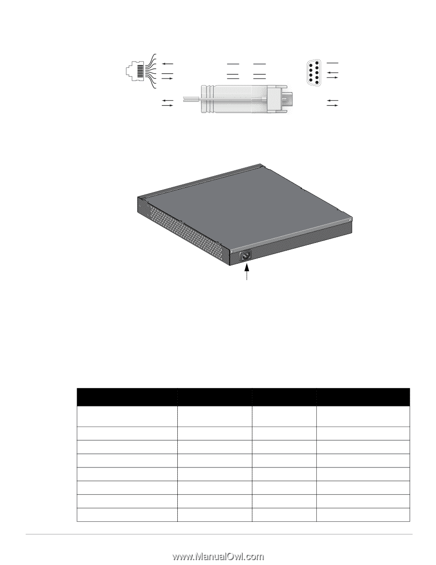
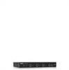
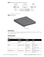
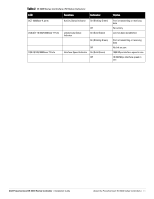
Figure 4 RJ-45 (female) to DB9 (male) Modular Adaptor Conversion RJ-45 Female Pin-Out 1 2 3 TxD 4 5 GND 6 RxD 7 8 Direction Input Output Internal Connections RJ-45 3 TxD 4 5 GND 6 RxD DB-9 2 5 3 DB-9 Male Pin-Out 9 8 7 6 5 4 3 2 1 Direction Input Output Ground RxD TxD Figure 5 represents the W-3200 rear view. Figure 5 W-3200 Rear View AC Power Socket AC Power Socket The W-3000 Series Controllers supports integrated AC powering and the AC power socket on the rear of the unit is for use with an AC power cord (country-specific). Refer to "Power Management Specifications" on page 17 for power specification details. LED Status Indicators Table 2 W-3000 Series Controllers LED Status Indicators LED Function Indicator POWER STATUS LNK 1000Base-X Ports Input Power Status Indicator Module Status Indicator Link Status Indicator On (Solid Green) Off On (Solid Green) On (Solid Red) On (Solid Amber) Off On (Solid Green) Off Status Power on No power Device is operational Device failed Device is loading software No power Link has been established No link on port 10 | About the PowerConnect W-3000 Series Controllers Dell PowerConnect W-3000 Series Controller | Installation Guide
-
 1
1 -
2
-
3
-
4
-
 5
5 -
 6
6 -
 7
7 -
 8
8 -
 9
9 -
 10
10 -
 11
11 -
 12
12 -
 13
13 -
 14
14 -
 15
15 -
16
-
17
-
18
-
19
-
20
 |
 |