Dell PowerConnect W-AP124 Dell PowerConnect AP-120-MNT-WJ Access Point Enclosu
Dell PowerConnect W-AP124 Manual
 |
View all Dell PowerConnect W-AP124 manuals
Add to My Manuals
Save this manual to your list of manuals |
Dell PowerConnect W-AP124 manual content summary:
- Dell PowerConnect W-AP124 | Dell PowerConnect AP-120-MNT-WJ Access Point Enclosu - Page 1
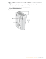
AP-120-MNT-WJ Access Point Enclosure Installation Guide Introduction The AP-120-MNT-WJ access point (AP) enclosure allows you to install an AP-121 or AP-125 access point on the wall, - Dell PowerConnect W-AP124 | Dell PowerConnect AP-120-MNT-WJ Access Point Enclosu - Page 2
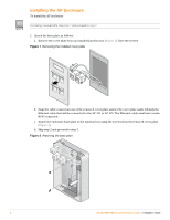
the removed cover plate (Figure 2). d. Skip step 2 and proceed to step 3. Figure 2 Attaching the base plate APenc_003 2 AP-120-MNT-WJ Access Point Enclosure | Installation Guide - Dell PowerConnect W-AP124 | Dell PowerConnect AP-120-MNT-WJ Access Point Enclosu - Page 3
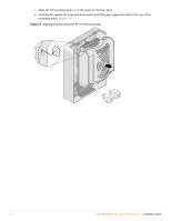
plate and the mounting holes on the AP (Figure 4). Figure 4 Preparing to attach the AP Mounting Posts AP-120-MNT-WJ Access Point Enclosure | Installation Guide APenc_004 Mounting Holes 3 - Dell PowerConnect W-AP124 | Dell PowerConnect AP-120-MNT-WJ Access Point Enclosu - Page 4
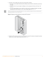
top of the mounting holes. (Figure 5) Figure 5 Aligning and securing the AP on the base plate APenc_005 4 AP-120-MNT-WJ Access Point Enclosure | Installation Guide - Dell PowerConnect W-AP124 | Dell PowerConnect AP-120-MNT-WJ Access Point Enclosu - Page 5
you plan on keeping the antennas hidden in the enclosure, skip this step and proceed to step 8. AP-120-MNT-WJ Access Point Enclosure | Installation Guide 5 - Dell PowerConnect W-AP124 | Dell PowerConnect AP-120-MNT-WJ Access Point Enclosu - Page 6
, clear the access cutouts marked B. c. Extend the antennas as necessary. Figure 7 Antenna openings A B Access cutout areas APenc_001 6 AP-120-MNT-WJ Access Point Enclosure | Installation Guide - Dell PowerConnect W-AP124 | Dell PowerConnect AP-120-MNT-WJ Access Point Enclosu - Page 7
. c. (Optional) place paper labels and clear windows over the LED and screw openings. Figure 8 Cover installation APenc_007 AP-120-MNT-WJ Access Point Enclosure | Installation Guide 7 - Dell PowerConnect W-AP124 | Dell PowerConnect AP-120-MNT-WJ Access Point Enclosu - Page 8
The following graphics show the completed installation. Figure 9 Wall mount with antennas extended Figure 10 Ceiling mount with antennas extended APenc_009 APenc_010 © 2010 Aruba Networks, Inc. All rights reserved. 8 July 2010 | 0510583-03
-
 1
1 -
 2
2 -
 3
3 -
 4
4 -
 5
5 -
 6
6 -
 7
7 -
8
 |
 |
AP-120-MNT-WJ Access Point Enclosure
Installation Guide
0510583-03
|
July 2010
1
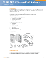
Introduction
The AP-120-MNT-WJ access point (AP) enclosure allows you to install an AP-121 or AP-125 access point
on the wall, directly over an installed junction box. Additionally, this enclosure can be mounted to the
ceiling, using ceiling tile rails.
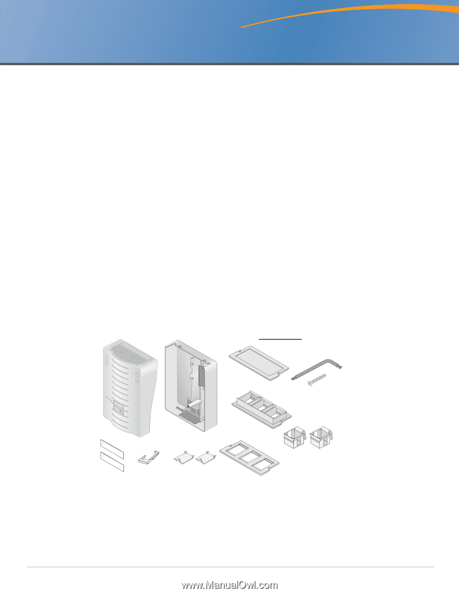
The AP-120-MNT-WJ kit includes the following pieces:
z
Plastic base to attach over a standard installed junction box or ceiling tile rail
z
Plastic enclosure cover
z
The following plastic connector plate styles:
±
1x Keystone connector plate
±
1x Siemon connector plate
±
1x Blank plate
z
Blank fillers for unused connectors
±
2x Keystone
±
2x Siemon
z
1x M4 x 25mm T-20 Torx screw
z
1x T-20 Torx key
z
1x white paper label sheet
z
2x clear window to cover labels
z
9/16" rail adapter
Additional Tools
z
A screwdriver that matches the screws in the cover plate over the installed junction box
z
(Optional) flat-head screwdriver or similar tool to punch out antenna access cutouts
Top Cover
Base
M4x25mm
Torx Screw
T-20 Torx Key
9/16” Rail
Adapter
Clear
Windows
Siemon Connector
Plate
Siemon 45*
Blanking Plates
Keystone
Blanking Plates
Keystone
Connector
Plate
Blank Plate
Parts not to scale