Dell PowerConnect W-AP124 Dell PowerConnect AP-120-MNT-WJ Access Point Enclosu - Page 5
Once the connector plate is secure, attach the connectors to the openings in the plate. Any empty
 |
View all Dell PowerConnect W-AP124 manuals
Add to My Manuals
Save this manual to your list of manuals |
Page 5 highlights
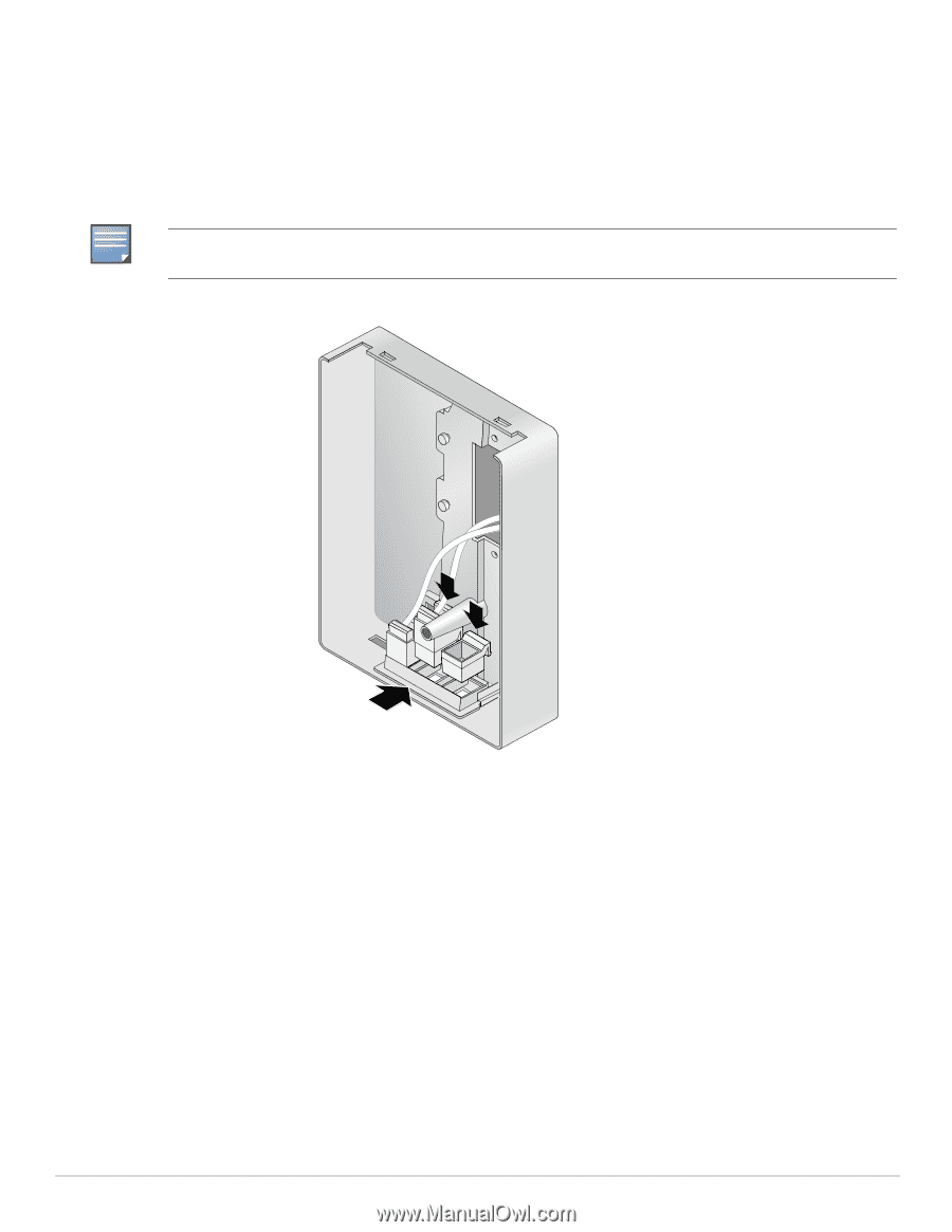
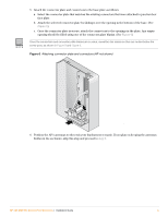
NOTE 5. Attach the connector plate and connectors to the base plate as follows: a. Select the connector plate that matches the existing connectors that were attached to junction box face plate. b. Attach the selected connector plate by sliding it over the opening in the bottom of the base. (See Figure 6). c. Once the connector plate is secure, attach the connectors to the openings in the plate. Any empty opening should be filled using one of the connector plate blanks. (See Figure 6) Once the connectors and connector plate blanks are in place, reposition the cables so they are routed below the screw post, as shown in Figure 8 and Figure 9. Figure 6 Attaching connector plate and connectors (AP not shown) APenc_006 6. Position the AP's antennas so they suit your deployment scenario. If you plan on keeping the antennas hidden in the enclosure, skip this step and proceed to step 8. AP-120-MNT-WJ Access Point Enclosure | Installation Guide 5
-
 1
1 -
 2
2 -
 3
3 -
 4
4 -
 5
5 -
 6
6 -
 7
7 -
 8
8
 |
 |