Dell PowerConnect W-Series FIPS Dell PowerConnect W-6000M3 and W-3000 Controll - Page 9
Chassis
 |
View all Dell PowerConnect W-Series FIPS manuals
Add to My Manuals
Save this manual to your list of manuals |
Page 9 highlights
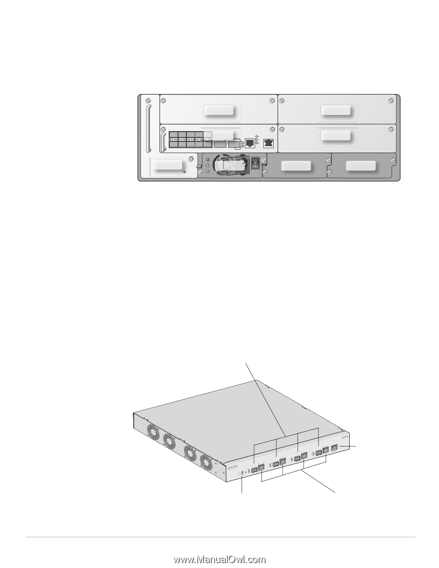
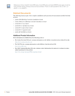
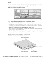
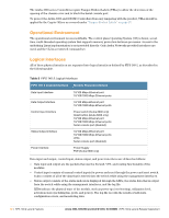
Chassis The Aruba 6000 Controller chassis is designed to be modular. All of the modular components, consisting of the switching supervisor and network line cards, the fan tray, and the power supplies, are accessible from the front of the chassis and are field replaceable and hot-swappable. Figure 1 The Aruba 6000 Controller with M3 Mark I Slot 2 Slot 0 Slot 3 Slot 1 Fan Tray PS1 PS2 PS3 arun_0118A Figure 1 shows the front of the Aruba 6000 Controller, and illustrates the following: Slots 2 and 3 are for optional Line Card modules to provide extra port capacity. Slots 0 and 1 are for one or two Multi-service Mobility Modules (M3), which combine the Supervisor Card and Line Card functionality in a single module. Note that this validation covers only configurations with one or two M3s. M3 indicator LEDs indicate power state, status of the device, and link activity. The hot-swappable fan tray cools the switch. The fan tray pulls air from right to left, as viewed from the front of the chassis, across the installed cards. PS1, PS2, and PS3 are for Power Supply modules. The number of power supplies required for the system depends on the number and type of Line Cards installed, and whether to include redundancy for fault tolerance. The Aruba 3000-series Controller chassis is a 1U not-modular chassis. Figure 2 The Aruba 3000-series Controller Chassis Optional 1000Base-X ports Serial Console Port System indicator LEDs Gigabit Ethernet ports Aruba 3000, 6000/M3 and Dell W-3000, W-6000M3 | FIPS 140-2 Level 2 Release Supplement The Aruba 3000 and 6000/M3 Controllers | 9
-
 1
1 -
2
-
3
-
 4
4 -
 5
5 -
 6
6 -
 7
7 -
 8
8 -
 9
9 -
 10
10 -
 11
11 -
 12
12 -
 13
13 -
 14
14 -
15
-
16
-
17
-
18
-
19
-
20
-
21
-
22
-
23
-
24
-
25
-
26
-
27
-
28
-
29
-
30
-
31
-
32
 |
 |