Dell PowerEdge 1900 Installing a SATA Optical Drive - Page 5
See the SATA optical drive into the tray until the pins on the carrier align with - replace drive
 |
View all Dell PowerEdge 1900 manuals
Add to My Manuals
Save this manual to your list of manuals |
Page 5 highlights
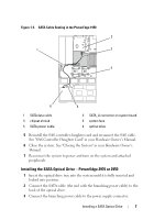
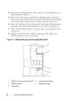
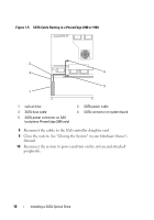
Figure 1-1. Replacing the Optical Drive in a PowerEdge 2950 or 2970 System 2 1 3 4 5 6 7 1 optical drive 3 interposer 5 SATA power cable 7 optical drive carrier 2 interposer release latch 4 SATA cable 6 carrier latch Replacing a PowerEdge 1950 Optical Drive NOTE: The replacement drive tray provided in the installation kit must be used with PowerEdge 1950 systems. If you are replacing an existing optical drive, do not reuse the interposer board attached to the old drive. Spread the side rails of the replacement drive tray and insert the back end of the SATA optical drive into the tray until the pins on the carrier align with the holes in the side of the drive. Release the rails to attach the drive to the tray. See Figure 1-2. Installing a SATA Optical Drive 5
-
 1
1 -
 2
2 -
 3
3 -
 4
4 -
 5
5 -
 6
6 -
 7
7 -
 8
8 -
 9
9 -
 10
10
 |
 |
