Dell PowerEdge 1900 Installing a SATA Optical Drive - Page 9
Installing the SATA Optical Drive - PowerEdge 2900 and 1900, Hardware Owner's Manual, Hardware Owner's
 |
View all Dell PowerEdge 1900 manuals
Add to My Manuals
Save this manual to your list of manuals |
Page 9 highlights
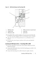
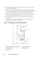
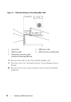
9 Replace the cooling shroud. See "Installing the Cooling Shroud" in your Hardware Owner's Manual. 10 Close the system. See "Closing the System" in your Hardware Owner's Manual. 11 Reconnect the system to power and turn on the system and attached peripherals. Installing the SATA Optical Drive - PowerEdge 2900 and 1900 1 If the mounting screws are not attached to the drive, install them now. 2 Align the mounting screws with the bay slide slots and insert the optical drive into the optical drive bay until the spring latch engages. 3 Connect the SATA cable to the back of the optical drive. 4 Use the appropriate power cable provided in the optical drive kit and connect one end to the optical drive and the other to the power supply as follows: - For a PowerEdge 2900 system, connect to the CD/TBU connector on the system backplane. See Figure 1-5. - For a PowerEdge 1900 system, connect to an available power supply cable. 5 Replace the center fan bracket. See "Replacing the Center Fan Bracket" in your Hardware Owner's Manual. 6 Replace the fans in the center fan bracket. 7 Route the SATA cable to the system board over the top of the fan bracket and connect the cable to the SATA connector on the system board. See Figure 1-5. - For a PowerEdge 2900, use the SATA_B connector. - For a PowerEdge 1900, use the SATA_D connector. Installing a SATA Optical Drive 9
-
 1
1 -
2
-
3
-
 4
4 -
 5
5 -
 6
6 -
 7
7 -
 8
8 -
 9
9 -
 10
10
 |
 |