Dell PowerEdge 1900 Installing a SATA Optical Drive - Page 8
Hardware Owner's Manual, Route the SATA cable along the top of the cable retention bracket to
 |
View all Dell PowerEdge 1900 manuals
Add to My Manuals
Save this manual to your list of manuals |
Page 8 highlights
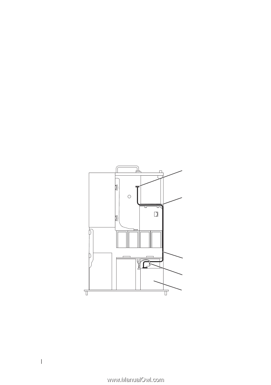
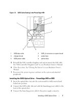
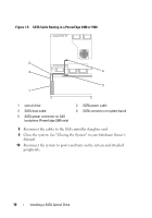
4 Remove the cooling shroud. See "Removing the Cooling Shroud" in your Hardware Owner's Manual. 5 Remove the cable retention bracket from the right interior wall of the chassis by pushing the blue release latch and sliding the bracket toward the front of the system until the bracket detaches from the chassis slots. 6 Route the SATA cable in the cable channel in the right wall of the chassis and replace the cable retention bracket over the cable. See Figure 1-4. 7 Route the SATA cable along the top of the cable retention bracket to the central riser. 8 Bend the cable behind the central riser and connect the cable to the SATA_B connector on the system board. Figure 1-4. SATA Cable Routing in the PowerEdge 2950 and 2970 1 2 3 4 5 1 SATA_B connector on system board 2 cable retention bracket 3 SATA data cable 4 SATA power cable 5 optical drive 8 Installing a SATA Optical Drive
-
 1
1 -
2
-
 3
3 -
 4
4 -
 5
5 -
 6
6 -
 7
7 -
 8
8 -
 9
9 -
 10
10
 |
 |