Dell PowerEdge 1900 Installing a SATA Optical Drive - Page 6
Installing the SATA Optical Drive - PowerEdge 1950 - replace sata drive
 |
View all Dell PowerEdge 1900 manuals
Add to My Manuals
Save this manual to your list of manuals |
Page 6 highlights
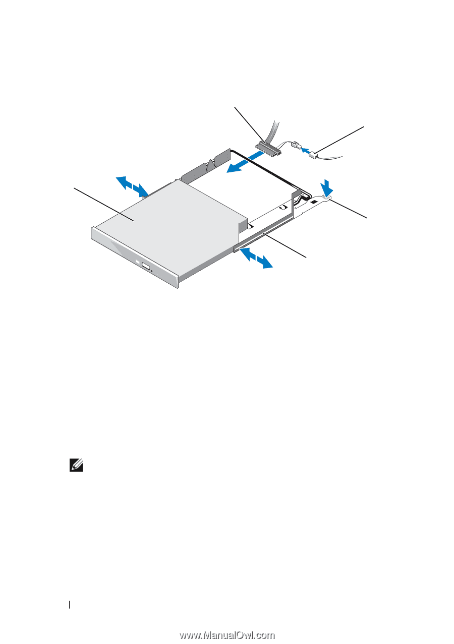
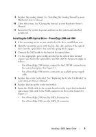
Figure 1-2. Installing a SATA Optical Drive in a PowerEdge 1950 Drive Tray 2 3 1 4 5 1 optical drive 3 SATA power cable 5 optical drive carrier 2 SATA cable 4 carrier latch Installing the SATA Optical Drive - PowerEdge 1950 1 Insert the optical drive tray into the system until it is fully inserted and locked into position. 2 Connect the SATA cable (the end with the branching power cable) to the back of the optical drive. 3 Connect the branching power cable to the power supply connector. NOTE: You may need to replace the existing power cable with a cable provided in the optical drive kit. 4 Route the SATA cable to the SATA_A connector on the system board. a Route the cable through the power cable cutout in the fan bracket and follow the power cable routing to the power supply bays. b Bend the cable toward the chipset shroud and insert the cable into the cable path on top of the chipset shroud. See Figure 1-3. c Connect the cable to the SATA_A connector on the system board. 6 Installing a SATA Optical Drive
-
 1
1 -
 2
2 -
 3
3 -
 4
4 -
 5
5 -
 6
6 -
 7
7 -
 8
8 -
 9
9 -
 10
10
 |
 |