Dell PowerEdge 2500 Rack-to-Tower Conversion Guide (.pdf) - Page 3
x 2 Backplane Installation, 1 x 2 Backplane Kit Contents, Before You Begin - power supply
 |
View all Dell PowerEdge 2500 manuals
Add to My Manuals
Save this manual to your list of manuals |
Page 3 highlights
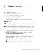
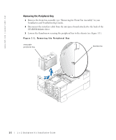
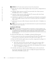
1 x 2 Backplane Installation This document provides instructions for installing a 1 x 2 backplane kit to add provisions for up to two additional 1-inch small computer system interface (SCSI) hard-disk drives in a Dell™ system's peripheral bay. 1 x 2 Backplane Kit Contents The 1 x 2 backplane kit includes the following items: • A 1 x 2 backplane attached to an assembled drive cage • Four 6-32 x 0.25-inch hex-head Phillips screws • Inter-integrated circuit (I2C) extension cable • Nonterminated SCSI cable that links the 1 x 2 backplane to the system board Before You Begin WARNING: Before you perform this procedure, you must turn off the system and disconnect it from its power source. For more information, read the safety precautions in your System Information document. WARNING: Your system may have more than one power supply cable. To reduce the risk of electrical shock, you must disconnect all power supply cables before servicing the system. For more information, see "Safety First-For You and Your Computer" in your Installation and Troubleshooting Guide. 1 Turn off the system, including any attached peripherals, and disconnect the system from the electrical outlet. CAUTION: See "Protecting Against Electrostatic Discharge" in the safety instructions in your System Information document. 2 Unpack the 1 x 2 backplane kit. 3 Remove the front bezel (see "Removing the Front Bezel" in your Installation and Troubleshooting Guide). 4 Remove the system cover (see "Removing the System Cover" in your Installation and Troubleshooting Guide). NOTE: Verify that your system has the latest basic input/output system (BIOS) revision and firmware. Download the latest revision from the Dell support site at http://support.dell.com. 1 x 2 Backplane Kit Installation Guide 1-1
-
 1
1 -
 2
2 -
 3
3 -
 4
4 -
 5
5 -
 6
6 -
 7
7 -
 8
8 -
 9
9 -
10
 |
 |