Dell PowerEdge 2500 Rack-to-Tower Conversion Guide (.pdf) - Page 8
PCI SCSI or PCI RAID controller card., Route the - raid configuration
 |
View all Dell PowerEdge 2500 manuals
Add to My Manuals
Save this manual to your list of manuals |
Page 8 highlights
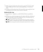
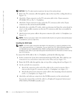
www.dell.com | support.dell.com NOTICE: The I2C cable must be routed over the top of the cooling shroud. 3 Route the I2C extension cable through the clips on the top of the cooling shroud (see Figure 1-3). 4 Attach the 10-pin connector on the I2C extension cable to the 10-pin connector (PLANAR_1X2) on the 1 x 2 backplane. 5 Attach the 20-pin connector on the end of the I2C extension cable to the 20-pin connector on the system board (PLANAR). 6 Attach the free end of the I2C cable, which was disconnected from the system board in step 1, to the middle connector on the new I2C extension cable that you installed in steps 3 and 4. 7 Attach a four-wire power cable to the power connector (J1) on the 1 x 2 backplane (see Figure 1-3). NOTE: The four-wire power cable is the standard cable found on all systems and provides power to peripherals, such as a tape drive. Installing the SCSI Cable NOTE: The SCSI cable installation described in this document is a typical installation of the SCSI cable used with the 1 x 2 backplane. You can install the SCSI cable differently, depending on redundant array of independent disks (RAID) configurations and the existence of SCSI peripheral cards. Refer to your operating system documentation for information on how to set up your SCSI devices. To connect the SCSI cable to the 1 x 2 backplane, perform the following steps: 1 In the customer kit, locate the nonterminated 68-pin SCSI cable. This cable has one connector on one end and two connectors on the other end (see Figure 1-3). 2 Route the SCSI cable through the clips on top of the cooling shroud (see Figure 1-3). 3 On the end with two connectors: a Attach the connector on the end of the cable to the vertical connector that is closest to the 10-pin I2C connector on the 1 x 2 backplane (see Figure 1-3). b Attach the next-to last connector on the cable to the remaining vertical connector on the 1 x 2 backplane (see Figure 1-3). 4 Attach the end with one connector to the SCSIB connector on the system board. You can also connect this end of the cable to a Peripheral Component Interconnect (PCI) SCSI or PCI RAID controller card. 1-6 1 x 2 Backplane Kit Installation Guide
-
 1
1 -
2
-
 3
3 -
 4
4 -
 5
5 -
 6
6 -
 7
7 -
 8
8 -
 9
9 -
 10
10
 |
 |