Dell PowerEdge 2500 Rack-to-Tower Conversion Guide (.pdf) - Page 6
Installing the Peripheral Bay - board
 |
View all Dell PowerEdge 2500 manuals
Add to My Manuals
Save this manual to your list of manuals |
Page 6 highlights
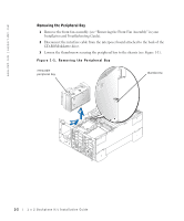
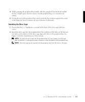
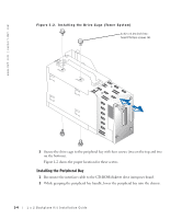
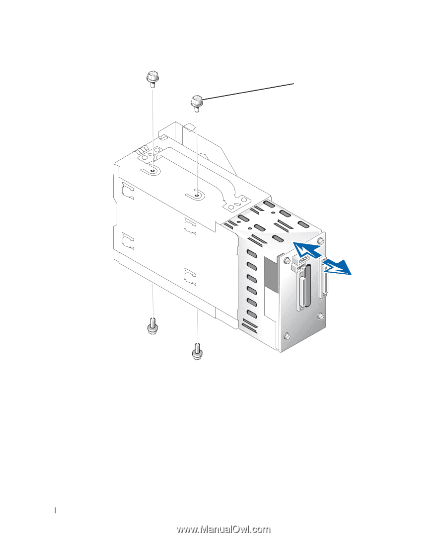
www.dell.com | support.dell.com Figure 1-2. Installing the Drive Cage (Tower System) 6-32 x 0.25-inch hexhead Phillips screws (4) 3 Secure the drive cage to the peripheral bay with four screws (two on the top and two on the bottom). Figure 1-2 shows the proper location for these screws. Installing the Peripheral Bay 1 Reconnect the interface cable to the CD-ROM/diskette drive interposer board. 2 While grasping the peripheral bay handle, lower the peripheral bay into the chassis. 1-4 1 x 2 Backplane Kit Installation Guide
-
 1
1 -
 2
2 -
 3
3 -
 4
4 -
 5
5 -
 6
6 -
 7
7 -
 8
8 -
 9
9 -
 10
10
 |
 |
1-4
1 x 2 Backplane Kit Installation Guide
www.dell.com | support.dell.com
Figure 1-2. Installing the Drive Cage (Tower System)
3
Secure the drive cage to the peripheral bay with four screws (two on the top and two
on the bottom).
Figure 1-2 shows the proper location for these screws.
Installing the Peripheral Bay
1
Reconnect the interface cable to the CD-ROM/diskette drive interposer board.
2
While grasping the peripheral bay handle, lower the peripheral bay into the chassis.
6-32 x 0.25-inch hex-
head Phillips screws (4)