Dell PowerEdge 2500 Rack-to-Tower Conversion Guide (.pdf) - Page 7
Installing the, Cable, Disconnect the - scsi
 |
View all Dell PowerEdge 2500 manuals
Add to My Manuals
Save this manual to your list of manuals |
Page 7 highlights
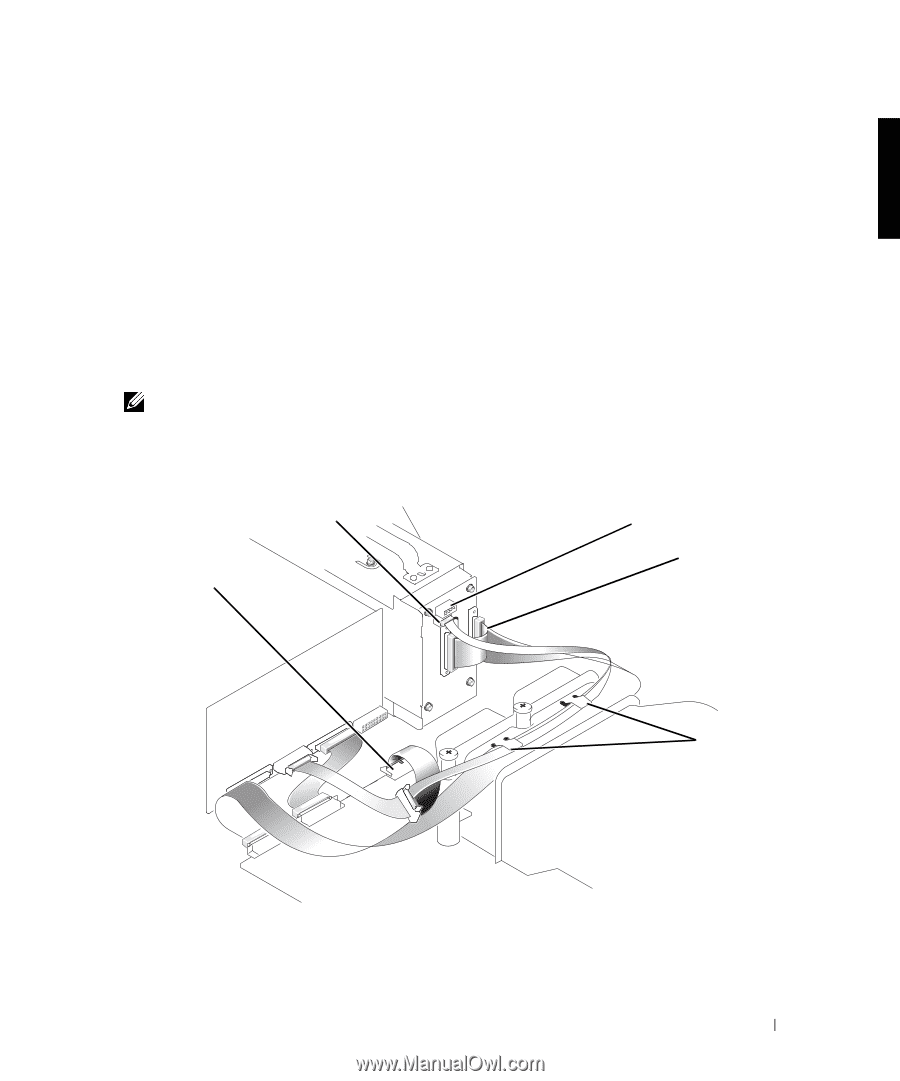
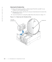
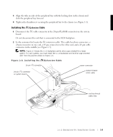
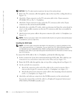
3 Align the tabs on side of the peripheral bay with the locking slots in the chassis and slide the peripheral bay forward. 4 Tighten the thumbscrew securing the peripheral bay to the chassis (see Figure 1-1). Installing the I2C Extension Cable 1 Disconnect the I2C cable connector at the 20-pin PLANAR connector on the system board. Do not disconnect the end that is connected to the SCSI backplane. 2 In the customer kit, locate the I2C extension cable. This cable has three connectors: a 20-pin connector on one end, a 10-pin connector on the other end, and a 20-pin cable connector in the middle (see Figure 1-3). NOTE: Figure 1-3 shows the 1 x 2 backplane and its drive cage oriented for a tower system. For rack systems, you must install the 1 x 2 backplane and its drive cage oriented 180° from the position shown in Figure 1-3. F i g u r e 1 - 3 . I n s t a l l i n g t h e I2C E x t e n s i o n C a b l e 10-pin I2C connector power connector 20-pin I2C connector on system board nonterminated SCSI cable cooling shroud cable clips 1 x 2 Backplane Kit Installation Guide 1-5
-
 1
1 -
 2
2 -
 3
3 -
 4
4 -
 5
5 -
 6
6 -
 7
7 -
 8
8 -
 9
9 -
 10
10
 |
 |