Dell PowerEdge C5220 Hardware Owner's Manual
Dell PowerEdge C5220 Manual
 |
View all Dell PowerEdge C5220 manuals
Add to My Manuals
Save this manual to your list of manuals |
Dell PowerEdge C5220 manual content summary:
- Dell PowerEdge C5220 | Hardware Owner's Manual - Page 1
Dell PowerEdge C5220 Systems Hardware Owner's Manual Regulatory Model: B04S - Dell PowerEdge C5220 | Hardware Owner's Manual - Page 2
A CAUTION indicates potential damage to hardware or loss of data if instructions are not followed. WARNING: A WARNING indicates a potential for property permission of Dell Inc. is strictly forbidden. Trademarks used in this text: Dell™, the DELL logo, and PowerEdge™ are trademarks of Dell Inc. Intel - Dell PowerEdge C5220 | Hardware Owner's Manual - Page 3
Features and Indicators 6 2 Using the System Setup Program 11 Start Menu 11 BIOS Setup Options at Boot 12 Console Redirection 12 Configuring Special Keys 13 General Help 14 Server Platform Setup Utility Screens 15 Main Menu 16 Advanced Menu 18 Server Management 33 - Dell PowerEdge C5220 | Hardware Owner's Manual - Page 4
Memory Modules 54 Hard Drives 59 Hard-Drive Boards 66 Heat Sinks 69 Processors 71 Mezzanine Cards 73 4 Troubleshooting 79 Troubleshooting Sequence 79 Update Utilities 83 BIOS System Update 89 BIOS Recovery Mode 89 5 Jumpers and Connectors 91 System Board Jumpers and Connectors 91 2.5- - Dell PowerEdge C5220 | Hardware Owner's Manual - Page 5
board + mezzanine card + 2.5-inch hard-drive board + cables. • 12-sled system board+ 3.5-inch hard-drive board + cables. • 12-sled system board + 2.5-inch hard-drive board + cables. NOTE: Mixed SATA and SAS hard drives on the 2.5 and 3.5-inch hard-drive board are not supported. About Your System 5 - Dell PowerEdge C5220 | Hardware Owner's Manual - Page 6
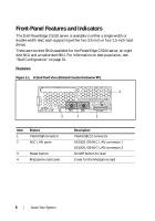
Front-Panel Features and Indicators The Dell PowerEdge C5220 server is available in either a single-width or double-width sled, each supporting either two 3.5-inch or four 2.5-inch hard drives. There are two sled SKUs available for the PowerEdge C5220 server, an eight sled SKU and a twelve sled SKU. - Dell PowerEdge C5220 | Hardware Owner's Manual - Page 7
Figure 1-2. 12-Sled Front Features (Rotated Counterclockwise 90°) 2 1 3 2 1 Item Feature Description 1 VGA/USB connector VGA/USB 2.0 connector 2 NIC LAN ports 10/100/1G NIC LAN connector 1 10/100/1G NIC LAN connector 2 3 Power button On/Off button for sled About Your System 7 - Dell PowerEdge C5220 | Hardware Owner's Manual - Page 8
Indicators Figure 1-3. 8-Sled Front View (Rotated Counterclockwise 90°) 4 32 1 20 31 7 65 Item Feature Status 1, 3 LAN link LED Off 2, 4 LAN activity LED Off LAN link LED Green LAN activity LED Off LAN link LED Green LAN activity LED Off - Dell PowerEdge C5220 | Hardware Owner's Manual - Page 9
Item Feature 6 Identity LED 7 Power/Status Status Blue On Blue Off Blinking blue Green On Green Off Amber Off Blinking amber 12-Sled LEDs (Rotated Counterclockwise 90°) 4 32 1 Description Identifies the system Normal status Identifies the system with an interval System DC On System DC Off - Dell PowerEdge C5220 | Hardware Owner's Manual - Page 10
Item Feature Status 1, 3 LAN link LED Off 2, 4 LAN activity LED Off LAN link LED Green LAN activity LED Off LAN link LED Green LAN activity LED Off - Dell PowerEdge C5220 | Hardware Owner's Manual - Page 11
latest AMI Core BIOS, which is stored in Flash memory. The Flash memory supports the plug-and-play specification, and contains a BIOS Setup program, the Power protection from unauthorized use • Protocol and feature enabling/disabling • Power Management features This Setup utility should be executed - Dell PowerEdge C5220 | Hardware Owner's Manual - Page 12
The console redirection allows a remote user to diagnose and fix problems on a server, which has not successfully booted to the OS. The centerpiece supports redirection of both video and keyboard through a serial link (serial port). After enabling console redirection, the local (host server - Dell PowerEdge C5220 | Hardware Owner's Manual - Page 13
which is limited to basic ASCII characters. There are no function keys, arrow keys, or control keys in this character set. However, the PowerEdge C5220 software requires the use of function keys and control keys for ordinary functions. You can emulate a function key or control key by using a special - Dell PowerEdge C5220 | Hardware Owner's Manual - Page 14
Key Page Down Reset ANSI Escape Sequence Other Sequences / Rr R General Help In addition to the Item Specific Help window, the Setup Utility also provides a General Help screen. This screen can be called up from any menu by pressing . The General Help screen lists the - Dell PowerEdge C5220 | Hardware Owner's Manual - Page 15
Server Platform Setup Utility Screens Conventions The following typographical conventions are used in the tables: • The text and values in the Setup Item, Options, and Help - Dell PowerEdge C5220 | Hardware Owner's Manual - Page 16
you enter BIOS Setup. Menu Fields Main System Date Settings MM/DD/YYYY System Time HH:MM:SS Product Name BIOS Version BIOS Build Date Service Tag 16 Using the System Setup Program Comments Set the Date. Use Tab to switch between Date elements. Set the time. Use Tab to switch - Dell PowerEdge C5220 | Hardware Owner's Manual - Page 17
Menu Fields Asset Tag MRC Version BMC Version FAN Control Board FW Settings ePPID NIC1 MAC Address NIC2 MAC Address BMC NIC MAC Address Processor Type Processor Speed Processor Core System Memory Size System Memory Speed Comments Displays the asset tag Displays the MRC version Displays the - Dell PowerEdge C5220 | Hardware Owner's Manual - Page 18
Advanced Menu The Advanced screen provides an access point to configure several options. On this screen, the user selects the option that is to be configured. Configurations are performed on the selected screen, not directly on the Advanced screen. CAUTION: Incorrect settings to items on the - Dell PowerEdge C5220 | Hardware Owner's Manual - Page 19
Menu Fields SATA Configuration Settings PCI Configuration USB Configuration Power Management Comments SATA Devices Configuration PCI, PCI-X and PCI Express Settings USB Configuration Menu Fields Settings Advanced \Power Management Power management Maximum Performance OS Control* Comments - Dell PowerEdge C5220 | Hardware Owner's Manual - Page 20
CPU Configuration Menu Fields Settings Advanced\CPU Configuration Active Processor Cores All* 1 2 4 6 8 Frequency Ratio Auto* 1 20 Using the System Setup Program Comments Number of cores to enable in each processor package Sets frequency multiplier as maximum level or downgrades - Dell PowerEdge C5220 | Hardware Owner's Manual - Page 21
Power C States. Set C1E disabled/enabled XD can prevent certain classes of malicious buffer overflow attacks when combined with a supporting OS (Microsoft Windows Server 2003 SP1, Windows XP SP2, SuSE Linux 9.2, Red Hat Enterprise Linux 3 Update 3, or later). Prefetch Configuration Using the System - Dell PowerEdge C5220 | Hardware Owner's Manual - Page 22
Prefetch Configuration Menu Fields Settings Comments Advanced\CPU Configuration\Prefetch Configuration Adjacent Cache Line Prefetch Disable Enable* To turn on/off prefetching of adjacent cache lines Hardware Prefetcher Disable Enable* To turn on/off the Mid Level Cache (L2) streamer - Dell PowerEdge C5220 | Hardware Owner's Manual - Page 23
running speed or set running speed up to 1066/1333 MHz. Memory remapping relocates memory space 3 GB~4 GB to the space above 4 GB with this feature disabled/enabled. Using the System Setup Program 23 - Dell PowerEdge C5220 | Hardware Owner's Manual - Page 24
SATA Configuration Menu Fields Settings Advanced\SATA Configuration Embedded SATA Off Controller IDE AHCI* SATA Port 0/SSI Hard drive 0 24 Using the System Setup Program Comments Disables the SATA controller or enables it and sets the device class code as IDE/AHCI. This token applies to - Dell PowerEdge C5220 | Hardware Owner's Manual - Page 25
. While entering setup, BIOS auto detects the presence of SATA devices and displays the status of detected SATA hard drives. Disable/Enable the feature that allows SATA hard drives to initiate link power management transitions. Not Set Security Freeze Lock Command Using the System Setup Program 25 - Dell PowerEdge C5220 | Hardware Owner's Manual - Page 26
Port Mapping of Cougar Point SATA Controllers to Hard Drive Board SATA Port0/SSI Hard drive 0 Unused in system SATA Port1/SSI Hard Drive 1 Unused in system SATA Port2/Hard Drive 0 Connected to hard drive 0 of 2.5/3.5-inch hard drive board SATA Port3/Hard Drive 1 Connected to hard drive 1 of - Dell PowerEdge C5220 | Hardware Owner's Manual - Page 27
VT for Direct I/O Disable* Enable Comments Embedded Network Devices Active State Power Management Configuration Disable/Enable Intel Virtualization Technology for Direct I/O (VT-d) that enhances I/O support (DMA) when running a Virtual Machine Monitor Using the System Setup Program 27 - Dell PowerEdge C5220 | Hardware Owner's Manual - Page 28
SR-IOV Global Enable Settings Disable* Enable Maximum Payload Size WHEA Support Auto* 128 Bytes 256 Bytes Disable* Enable Comments Disable/Enable BIOS support for SR-IOV devices. To enable this feature, an add-on NIC with SR-IOV support is required. Auto detects the PCIe maximum payload size or - Dell PowerEdge C5220 | Hardware Owner's Manual - Page 29
Embedded Network Devices Menu Fields Settings Comments Advanced\PCI Configuration\Embedded Network Devices Embedded NIC1 Disabled Enabled with PXE* Enabled without PXE iSCSI Remote Boot Disable/Enable the system's primary embedded network interface controller (full-function), w/, w/o - Dell PowerEdge C5220 | Hardware Owner's Manual - Page 30
Menu Fields Embedded NIC2 Settings Disabled Enabled with PXE Enabled without PXE* iSCSI Remote Boot Active State Power Management Configuration Comments Disables/Enables the system's secondary embedded network interface controller (fullfunction), w/, w/o including its PXE boot-ROM or with iSCSI - Dell PowerEdge C5220 | Hardware Owner's Manual - Page 31
Power Management Configuration Onboard LAN ASPM Disabled* L0s L0s & L1 Controls the level of ASPM supported on the PCI Express Link Mezzing Slot ASPM Disabled* L0s L0s & L1 Controls the level of ASPM supported on the PCI Express Link NB-SB Port ASPM Disabled L0s & L1* Controls the level - Dell PowerEdge C5220 | Hardware Owner's Manual - Page 32
PORT Disabled Enabled* Disabled Enabled* Disabled Enabled* Comments Disables/Enables the builtin USB controller at system startup. Enables Legacy USB support. Disable option keeps USB devices available only for EFI applications. Allows the users to electrically disable/enable the internal USB port - Dell PowerEdge C5220 | Hardware Owner's Manual - Page 33
Management Menu Fields Server Management ACPI SPMI Table Set BMC LAN Configuration Remote Access Configuration Restore on AC Power Loss Settings Disabled Enabled* Power Off Power On* Last State - Dell PowerEdge C5220 | Hardware Owner's Manual - Page 34
Menu Fields Power Staggering AC Recovery Settings Immediate* Random User Defined Power Button View BMC System Event Log Clear BMC System Event Log Event logging Disabled Enabled* Disabled Enabled* NMI On Error Disabled Enabled* Comments Immediate: PowerOn (No Delay)\Random: (Auto)\User Defined - Dell PowerEdge C5220 | Hardware Owner's Manual - Page 35
Set BMC LAN Configuration Menu Fields Settings Server Management/BMC Network Configuration BMC LAN Port Configuration Dedicated-NIC Shared-NIC* BMC NIC IP Source Static DHCP* Comments BMC LAN Port Configuration NOTE: Dedicated- - Dell PowerEdge C5220 | Hardware Owner's Manual - Page 36
Menu Fields IP Address Settings xxx.xxx.xxx.xxx Subnet Mask xxx.xxx.xxx.xxx GateWay Address xxx.xxx.xxx.xxx Comments Enter IP address in the form of XXX.XXX.XXX.XXX (XXX less than 256 and in decimal only). Enter Subnet Mask in the form of XXX.XXX.XXX.XXX (XXX less than 256 and in decimal only - Dell PowerEdge C5220 | Hardware Owner's Manual - Page 37
Remote Access Configuration Menu Fields Settings Server/Remote Access Configuration Remote Access Disabled Enabled* Comments The settings specify how the host would keep 100x31 even when Remote Access is enabled. Client console utility should be supported. Using the System Setup Program 37 - Dell PowerEdge C5220 | Hardware Owner's Manual - Page 38
* Redirection After BIOS POST Terminal Type ANSI* VT100 VT-UTF8 Emulation: ANSI: Extended ASCII char set. VT100: ASCII char set. VT100+: Extends VT100 to support color, function keys, etc. VT-UTF8: Uses UTF8 encoding to map Unicode chars onto 1 or more bytes. NOTE: BIOS setup screens display at - Dell PowerEdge C5220 | Hardware Owner's Manual - Page 39
View BMC System Event Log NOTE: Only provides a brief SEL description for the user. If the user needs more detailed information, refer to the BMC Event Log in the Server Health of WebUI. Using the System Setup Program 39 - Dell PowerEdge C5220 | Hardware Owner's Manual - Page 40
Boot Menu This page enables you to set POST boot parameters. Menu Fields Boot Quiet Boot Pause On Errors Force PXE Boot Only Settings Disabled Enabled* Disabled* Enabled Disabled* Enabled Comments Enables or disables Quiet Boot option Pause on Errors Force PXE Boot Only 40 Using the System - Dell PowerEdge C5220 | Hardware Owner's Manual - Page 41
Menu Fields Boot Mode 1st Boot 2nd Boot 3rd Boot 4th Boot 5th Boot Settings BIOS* UEFI Network* Hard Disk RAID USB Storage CD/DVD Network Hard Disk* RAID USB Storage CD/DVD Network Hard Disk RAID* USB Storage CD/DVD Network Hard Disk RAID USB Storage* CD/DVD Network Hard Disk RAID USB Storage CD/ - Dell PowerEdge C5220 | Hardware Owner's Manual - Page 42
Security Menu Menu Fields Security Change Supervisor Password Change User Password Settings Comments Set Supervisor Password Set User Password 42 Using the System Setup Program - Dell PowerEdge C5220 | Hardware Owner's Manual - Page 43
Save and Exit Menu Fields Save & Exit Save Change and Exit Settings Discard Changes and Exit Save Changes Discard Changes Comments Exit system setup after saving the changes. Exit system setup without saving any changes. Save Changes done so far to any of the setup option. Discard changes done - Dell PowerEdge C5220 | Hardware Owner's Manual - Page 44
Launch EFI Shell application (Shellx64.efi) from one of the available file system devices. NOTE: For further specifications see UEFI Shell Specification at uefi.org/specs/. 44 Using the System Setup Program - Dell PowerEdge C5220 | Hardware Owner's Manual - Page 45
POST Error Handling This section provides information on POST error message and handling. Error Messages Error messages are displayed at POST under the following fail conditions: • Hard drive is not present in system • MRC initialization failure in a DIMM module NOTE: You can enable the Pause on - Dell PowerEdge C5220 | Hardware Owner's Manual - Page 46
Code 0x90 0x91 0x92 0x94 0x95 0x96 0x97 0x98 0x99 0x9A 0x9B 0x9C Status Codes Description Boot Device Selection (BDS) phase is started Driver connecting is started PCI Bus initialization is started PCI Bus Enumeration PCI Bus Request Resources PCI Bus Assign Resources Console Output devices connect - Dell PowerEdge C5220 | Hardware Owner's Manual - Page 47
started SCSI Reset SCSI Detect SCSI Enable Setup Verifying Password Start of Setup Setup Input Wait Ready To Boot event Legacy Boot event Exit Boot Services event Legacy Option ROM Initialization System Reset USB hot plug Using the System Setup Program 47 - Dell PowerEdge C5220 | Hardware Owner's Manual - Page 48
48 Using the System Setup Program - Dell PowerEdge C5220 | Hardware Owner's Manual - Page 49
should only perform troubleshooting and simple repairs as authorized in your product documentation, or as directed by the online or telephone service and support team. Damage due to servicing that is not authorized is not covered by warranty. Read and follow the safety instructions that came with - Dell PowerEdge C5220 | Hardware Owner's Manual - Page 50
should only perform troubleshooting and simple repairs as authorized in your product documentation, or as directed by the online or telephone service and support team. Damage due to servicing that is not authorized is not covered by warranty. Read and follow the safety instructions that came with - Dell PowerEdge C5220 | Hardware Owner's Manual - Page 51
support team. Damage due to servicing that is not authorized by Dell is not covered by your warranty. Read and follow the safety instructions that came with the product. The following illustrations show the two server sled options and the sled numbering in each option. Figure 3-2. PowerEdge C5220 - Dell PowerEdge C5220 | Hardware Owner's Manual - Page 52
only perform troubleshooting and simple repairs as authorized in your product documentation, or as directed by the online or telephone service and support team. Damage due to servicing that is not authorized by Dell is not covered by your warranty. Read and follow the safety instructions that came - Dell PowerEdge C5220 | Hardware Owner's Manual - Page 53
only perform troubleshooting and simple repairs as authorized in your product documentation, or as directed by the online or telephone service and support team. Damage due to servicing that is not authorized by Dell is not covered by your warranty. Read and follow the safety instructions that came - Dell PowerEdge C5220 | Hardware Owner's Manual - Page 54
Memory Supported Memory Configura- Memory Type/Size CPU DIMMs Type tion Memory Rank Type Speed (x8, x4) (MHz) Component Total DIMM Slot Density Size A1 A2 A3 A4 8-Sled DDR3 ECC 1 1 UDIMM 1333 1R x8 2 Gb 2G • UDIMM/2048 MB*1 8-sled DDR3 ECC 1 2 UDIMM 1333 1R x8 2 Gb 4G - Dell PowerEdge C5220 | Hardware Owner's Manual - Page 55
Supported Memory Configura- Memory Type/Size CPU DIMMs Type tion Memory Rank Type Speed (x8, x4) (MHz) 8-sled DDR3 ECC 1 4 UDIMM/2048 MB*4 8-sled DDR3 ECC 1 1 UDIMM/4096 MB*1 8-sled DDR3 ECC 1 2 UDIMM/4096 MB*2 8-sled DDR3 ECC 1 4 UDIMM/2048 MB*2 +4096 MB*2 8-sled DDR3 - Dell PowerEdge C5220 | Hardware Owner's Manual - Page 56
2G 4G 2G 2G 12 sled DDR3 ECC 1 4 troubleshooting and simple repairs as authorized in your product documentation, or as directed by the online or telephone service and support team. Damage due to servicing that is not authorized is not covered by warranty. Read and follow the safety instructions - Dell PowerEdge C5220 | Hardware Owner's Manual - Page 57
Figure 3-5. Removing and Installing a Memory Module 1 2 3 1 locking latch 3 memory module notch 2 DIMM slot Installing System Components 57 - Dell PowerEdge C5220 | Hardware Owner's Manual - Page 58
should only perform troubleshooting and simple repairs as authorized in your product documentation, or as directed by the online or telephone service and support team. Damage due to servicing that is not authorized is not covered by warranty. Read and follow the safety instructions that came with - Dell PowerEdge C5220 | Hardware Owner's Manual - Page 59
only perform troubleshooting and simple repairs as authorized in your product documentation, or as directed by the online or telephone service and support team. Damage due to servicing that is not authorized by Dell is not covered by your warranty. Read and follow the safety instructions that came - Dell PowerEdge C5220 | Hardware Owner's Manual - Page 60
2.5" HDD 2.5" HDD 2.5" HDD 2.5" HDD HDD0 HDD1 HDD2 HDD3 4 Remove the four screws from the 2.5-inch hard-drive bracket, then detach the hard drive from the bracket. 60 Installing System Components - Dell PowerEdge C5220 | Hardware Owner's Manual - Page 61
orientation of the bracket with the arrow mark pointing towards the hard drive connector. 2 Connect the hard drive to the hard-drive board in the sled. 2.5" HDD 2.5" HDD 2.5" HDD 2.5" HDD HDD0 HDD1 HDD2 HDD3 3 Replace the - Dell PowerEdge C5220 | Hardware Owner's Manual - Page 62
only perform troubleshooting and simple repairs as authorized in your product documentation, or as directed by the online or telephone service and support team. Damage due to servicing that is not authorized by Dell is not covered by your warranty. Read and follow the safety instructions that came - Dell PowerEdge C5220 | Hardware Owner's Manual - Page 63
3 Remove the hard drive cables from the cable clips. Top of sled 3.5" HDD HDD0 3.5" HDD HDD1 4 Disconnect the hard drive cables from the hard drive board and system board then lift the hard drive out of the sled . 2 3.5" HDD HDD0 HDD0 3.5" HDD HDD1 HDD1 1 HDD1 HDD0 SATA1 SATA0 Installing - Dell PowerEdge C5220 | Hardware Owner's Manual - Page 64
from the hard drive. Installing a 3.5-inch Hard Drive 1 Connect the hard drive cables A and B to a new hard drive. 2 Place the hard drive in the sled then connect the hard drive cables to the hard-drive board and system board . 1 3.5" HDD HDD0 HDD0 3.5" HDD HDD1 HDD1 2 64 Installing System - Dell PowerEdge C5220 | Hardware Owner's Manual - Page 65
3 Insert the hard drive cables into the cable clips. 3.5" HDD HDD0 3.5" HDD HDD1 4 Replace the hard-drive bracket screws underneath the sled. Installing System Components 65 - Dell PowerEdge C5220 | Hardware Owner's Manual - Page 66
only perform troubleshooting and simple repairs as authorized in your product documentation, or as directed by the online or telephone service and support team. Damage due to servicing that is not authorized by Dell is not covered by your warranty. Read and follow the safety instructions that came - Dell PowerEdge C5220 | Hardware Owner's Manual - Page 67
in the sled and connect troubleshooting and simple repairs as authorized in your product documentation, or as directed by the online or telephone service and support team. Damage due to servicing that is not authorized by Dell is not covered by your warranty. Read and follow the safety instructions - Dell PowerEdge C5220 | Hardware Owner's Manual - Page 68
Installing a 3.5-inch Hard-Drive Board 1 Unpack the new hard-drive board. 2 Holding the board by the edges, place the hard-drive board into the sled and connect to the system board . 3 Replace the eight screws to secure in place . 68 Installing System Components - Dell PowerEdge C5220 | Hardware Owner's Manual - Page 69
only perform troubleshooting and simple repairs as authorized in your product documentation, or as directed by the online or telephone service and support team. Damage due to servicing that is not authorized by Dell is not covered by your warranty. Read and follow the safety instructions that came - Dell PowerEdge C5220 | Hardware Owner's Manual - Page 70
Installing a Heat Sink 1 Place the new heatsink onto the system board . 2 Tighten the four captive screws of the heatsink . 70 Installing System Components - Dell PowerEdge C5220 | Hardware Owner's Manual - Page 71
only perform troubleshooting and simple repairs as authorized in your product documentation, or as directed by the online or telephone service and support team. Damage due to servicing that is not authorized by Dell is not covered by your warranty. Read and follow the safety instructions that came - Dell PowerEdge C5220 | Hardware Owner's Manual - Page 72
Installing a Processor CAUTION: Positioning the processor incorrectly can permanently damage the system board or the processor. Be careful not to bend the pins in the socket. 1 Place the new processor into the socket. 2 Close the locking latch. 72 Installing System Components - Dell PowerEdge C5220 | Hardware Owner's Manual - Page 73
should only perform troubleshooting and simple repairs as authorized in your product documentation, or as directed by the online or telephone service and support team. Damage due to servicing that is not authorized is not covered by warranty. Read and follow the safety instructions that came with - Dell PowerEdge C5220 | Hardware Owner's Manual - Page 74
Board in a Mezzanine Card 5 4 2 3 6 Flip the mezzanine assembly over and align over the two guide pins on the sled, see following image. Figure 3-7. Installing a Mezzanine Assembly in a Sled 6 NOTE: The I/O screw bracket tab must be behind the mezzanine bracket. 7 Align the linking board over - Dell PowerEdge C5220 | Hardware Owner's Manual - Page 75
assembly with the provided screw. Installing the SAS Mezzanine Card Prior to installing a mezzanine card, you must first remove the sled board from the chassis, see "Removing a Sled" on page 52. 1 Remove the mezzanine card from its static-proof packing. 2 With the PCIe connector facing up, attach - Dell PowerEdge C5220 | Hardware Owner's Manual - Page 76
in a SAS Mezzanine Card 6 5 2 3 4 7 Flip the mezzanine assembly over and align over the two guide pins on the sled, see following image. Figure 3-10. Installing a SAS Mezzanine Assembly in a Sled 8 9 7 NOTE: The I/O screw bracket tab must be behind the mezzanine bracket. 8 Align the linking - Dell PowerEdge C5220 | Hardware Owner's Manual - Page 77
Routing the SAS Mezzanine Cables After installing a mezzanine card, you need to route the SAS cabling as depicted in the following figure. Figure 3-11. SAS Mezzanine Cable Routing hard drive ports routing path Installing System Components 77 - Dell PowerEdge C5220 | Hardware Owner's Manual - Page 78
78 Installing System Components - Dell PowerEdge C5220 | Hardware Owner's Manual - Page 79
4 Troubleshooting Troubleshooting Sequence Server Boot Issues System Does Not Boot After Initial Software Changes BIOS Changes Viewing System Event Logs for Investigation Installation Problems Troubleshooting External Connections System Does Not Boot After Initial Installation Power Connector - Dell PowerEdge C5220 | Hardware Owner's Manual - Page 80
. Refer to the monitor's documentation to confirm operation. If the problem still persists, test or replace the monitor on a different AC supply are compatible with the processor model. Table 4-1. Supported Processor List for the C5220 Intel Xeon E3-1200 Product Family Intel Xeon E3- Troubleshooting - Dell PowerEdge C5220 | Hardware Owner's Manual - Page 81
one at a time to isolate which one is causing the problem. If the problem occurs even after removing the non-essential components, the problem has to be with the system board, power supply, memory, components, verify that the component installed is compatible with the system. Troubleshooting 81 - Dell PowerEdge C5220 | Hardware Owner's Manual - Page 82
you can now boot normally, there may be a compatibility issue between the new software or driver and some component in your system. Contact the software manufacturer for assistance. BIOS Changes Changes . For more information, see "View BMC System Event Log" on page 39. 82 Troubleshooting - Dell PowerEdge C5220 | Hardware Owner's Manual - Page 83
AC power. Check the AC power cord to make sure that it is securely connected. Troubleshooting External Connections Loose or improperly connected cables are the most likely source of problems for the system, monitor, and other peripherals (such as a printer, keyboard, mouse, or other external - Dell PowerEdge C5220 | Hardware Owner's Manual - Page 84
• option=f|2|c - skip the comparison of flash data and force to update - use chip erase instead of sector erase - reset scratch - two flash update support AST2050: two SPI solution: 1st SPI is on CS2; 2nd SPI is on CS0 Examples: Flash All without Saving user configuration Data: C:\socflash \dosflash - Dell PowerEdge C5220 | Hardware Owner's Manual - Page 85
DOS. c:\socflash\> dos.bat After the procedure is complete, wait 90 seconds for BMC to reset. Instructions for Windows 2008 64bit win.bat: Change directory to .\socflash Execute win.bat on Local System with 0x02 0x01 0x10 0x02 0x00 0x00 0x00 0xff >10 02 00 01 07 4 Set URL. Troubleshooting 85 - Dell PowerEdge C5220 | Hardware Owner's Manual - Page 86
ASCII code for URL - " ftp://user:[email protected]/s2gv112.bin" Response: 2a written data length TFTP Server Update (Ex: tftp://192.168.1.111/s2gv112.bin) >ipmitool -H -I lanplus -U root -P raw 0x08 0x01 0x01 0x80 0x00 Response: 34 firmware update task ID 86 Troubleshooting - Dell PowerEdge C5220 | Hardware Owner's Manual - Page 87
as followed: 0x00: Transmitting Image 0x01: Validating Image 0x02: Programming 0x03: Ready to Accept Image 0x04: USB Unit Stage 0x05: Connecting to server 0x80: General Error 0x81: Cannot establish connection 0x82: Path not found 0x83: Transmission Abort 0x84: Checksum Error Troubleshooting 87 - Dell PowerEdge C5220 | Hardware Owner's Manual - Page 88
0x85: Incorrect Platform 0x86: Allocate memory failed 0x87: Virtual media detach failed 0xFF: Completed Restart firmware while status code is 0xFF >ipmitool -H -I lanplus -U root -P root raw 0x06 0x02 88 Troubleshooting - Dell PowerEdge C5220 | Hardware Owner's Manual - Page 89
local interface. 1 Boot into DOS/Microsoft Windows. 2 Execute C5220BIOS(version).exe. NOTE: DOS does not support long file names. To use a file under DOS mode, rename it to fit the required file structure the USB device. 2 Short the recovery jumper (JP11). 3 Power on the system. Troubleshooting 89 - Dell PowerEdge C5220 | Hardware Owner's Manual - Page 90
4 The BIOS boots into the BIOS setup menu and the Recovery page appears. 5 Select Proceed with flash update. 90 Troubleshooting - Dell PowerEdge C5220 | Hardware Owner's Manual - Page 91
5 Jumpers and Connectors System Board Jumpers and Connectors Figure 5-1 displays the system components on the system board. Figure 5-1. System Board Diagram Back 20 19 1 18 17 16 2 3 15 4 14 5 6 13 7 12 8 9 11 10 Front Jumpers and Connectors 91 - Dell PowerEdge C5220 | Hardware Owner's Manual - Page 92
board connectors (PCI-e x4) 3 SDHC module (System supports one SDHC card) 5 ME recovery mode header (JP10) BMC COM port switch header (JP3/JP4) 6 COM port connector (J9) 8 Mezzanine card connector (8-sled only) 10 VGA/USB connector 12 Battery socket 14 NVRAM clear setting (JP5) 16 SATA connectors ( - Dell PowerEdge C5220 | Hardware Owner's Manual - Page 93
2.5-inch Hard-Drive Board Connectors Figure 5-2 shows the connectors on the 2.5-inch hard-drive board. Figure 5-2. 2.5-inch Hard-Drive Board 1 2 3 1 backplane connector 3 hard drive 1 connector 5 hard drive 3 connector 7 hard drive 0 SATA connector 9 hard drive 2 SATA connector 10 6 9 8 6 - Dell PowerEdge C5220 | Hardware Owner's Manual - Page 94
3 hard drive 1 power connector Backplane Connectors 2 hard drive 0 power connector 4 two board-edge connectors 8-Sled Backplane Front Connectors Figure 5-4 shows the 8-sled backplane front connectors. Figure 5-4. 8-Sled Backplane Front Connectors 1 2 3 4 5 6 7 8 94 Jumpers and Connectors - Dell PowerEdge C5220 | Hardware Owner's Manual - Page 95
1 sled 1 connector 3 sled 3 connector 5 sled 5 connector 7 sled 7 connector 2 sled 2 connector 4 sled 4 connector 6 sled 6 connector 8 sled 8 connector 8-Sled Backplane Back Connectors Figure 5-5 shows the connectors on the back of the backplane. Figure 5-5. 8-Sled SKU Backplane Back Connectors - Dell PowerEdge C5220 | Hardware Owner's Manual - Page 96
8 9 10 11 12 1 sled 1 connector 3 sled 3 connector 5 sled 5 connector 7 sled 7 connector 9 sled 9 connector 11 sled 11 connector 2 sled 2 connector 4 sled 4 connector 6 sled 6 connector 8 sled 8 connector 10 sled 10 connector 12 sled 12 connector 12-Sled Backplane Back Connectors Figure 5-7 shows - Dell PowerEdge C5220 | Hardware Owner's Manual - Page 97
connector 4 6 fan connector 5 8 fan connector 6 10 PSU 2 connector 12 fan connector 8 14 PMBus 1 connector 16 LAN connector Table 5-3. 12-Sled Backplane Jumper Positions MD2 MD1 Mode 0 1 Normal 1 1 JTAG 1 0 Boot Power Distribution Board Connectors Figure 5-8 shows the connectors on the - Dell PowerEdge C5220 | Hardware Owner's Manual - Page 98
PDB Power and SMBus Connectors This section provides information on the PDB power and SMBus connector pin out. Table 5-4. PDB Power and SMBus Connector Pin Out Pin Signal Pin Signal 1 +12V 2 +12V 3 +12V 4 +12V 5 +12V 6 +12V 7 +12V 8 +12V 9 +12V 10 CSHARE 11 PS_PRESENT_0 12 - Dell PowerEdge C5220 | Hardware Owner's Manual - Page 99
provides several online and telephone-based support and service options. Availability varies by country and product, and some services may not be available in your area. To contact Dell for sales, technical support, or customer service issues: 1 Visit support.dell.com. 2 Click your country/region at - Dell PowerEdge C5220 | Hardware Owner's Manual - Page 100
100 Getting Help - Dell PowerEdge C5220 | Hardware Owner's Manual - Page 101
advanced 18 boot menu 40 power management 19 security menu 42 server management 33 board 2.5-inch hard drive 73 3.5-inch hard drive sled 51 supported DIMM 54 connector system board 91 connectors 12-sled backplane 96 2.5-inch hard-drive board 93 3.5-inch hard-drive board 94 8-sled backplane 94 8-sled - Dell PowerEdge C5220 | Hardware Owner's Manual - Page 102
Dell 99 D Dell contacting 99 DIMM configuration 54 population rules 54 G getting help 99 H handling supply 80 K keys configuration 13 special 13 M management power 19 server 33 measures safety 49 memory installing modules 58 removing 56 supported 54 menu advanced 18 boot 40 main menu BIOS main 16 - Dell PowerEdge C5220 | Hardware Owner's Manual - Page 103
12 P population DIMM 54 power distribution doard 97 problems installation 83 processor replacing 71 program system setup 11 server setup 15 setup 15 setup program using 11 sled configuration 51 removing 52 start menu start 11 support services 99 system inside 50 T tools recommended 49 troubleshooting - Dell PowerEdge C5220 | Hardware Owner's Manual - Page 104
104
-
 1
1 -
 2
2 -
 3
3 -
 4
4 -
 5
5 -
 6
6 -
 7
7 -
8
-
9
-
10
-
11
-
12
-
13
-
14
-
15
-
16
-
17
-
18
-
19
-
20
-
21
-
22
-
23
-
24
-
25
-
26
-
27
-
28
-
29
-
30
-
31
-
32
-
33
-
34
-
35
-
36
-
37
-
38
-
39
-
40
-
41
-
42
-
43
-
44
-
45
-
46
-
47
-
48
-
49
-
50
-
51
-
52
-
53
-
54
-
55
-
56
-
57
-
58
-
59
-
60
-
61
-
62
-
63
-
64
-
65
-
66
-
67
-
68
-
69
-
70
-
71
-
72
-
73
-
74
-
75
-
76
-
77
-
78
-
79
-
80
-
81
-
82
-
83
-
84
-
85
-
86
-
87
-
88
-
89
-
90
-
91
-
92
-
93
-
94
-
95
-
96
-
97
-
98
-
99
-
100
-
101
-
102
-
103
-
104
 |
 |

Dell PowerEdge C5220
Systems
Hardware Owner’s
Manual
Regulatory Model: B04S