Dell PowerEdge C5220 Hardware Owner's Manual - Page 92
Table 5-1., System Board Jumper Settings, Jumper, Description, Default Setting, Function
 |
View all Dell PowerEdge C5220 manuals
Add to My Manuals
Save this manual to your list of manuals |
Page 92 highlights
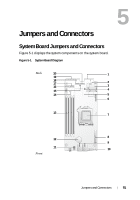
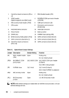
1 Hard drive board connectors (PCI-e x4) 3 SDHC module (System supports one SDHC card) 5 ME recovery mode header (JP10) 7 CPU socket 9 NIC1/NIC2 RJ45 connector 11 Power button 13 DIMM slots 15 BIOS recovery mode jumper (JP11) 17 SATA connectors (hard drive 1) 19 Hard drive board connectors (PCI-e x8) 2 BMC disable header (JP1) 4 BIOS/BMC COM port switch header (JP3/JP4) 6 COM port connector (J9) 8 Mezzanine card connector (8-sled only) 10 VGA/USB connector 12 Battery socket 14 NVRAM clear setting (JP5) 16 SATA connectors (hard drive 0) 18 SATA connectors (hard drive 2) 20 SATA connectors (hard drive 3) Table 5-1. System Board Jumper Settings Jumper Description Default Setting Function JP1 BMC disable header Open (JP1) Debug only Do not install jumper JP3/4 BIOS/BMC COM port jumper 1&2: BIOS COM 1&2: BIOS COM port header (Default) 2&3: BMC debug header JP5 NVRAM clear 1&2: Hold 1&2: Hold (Default) 2&3: Clear NVRAM & password JP10 ME recovery mode Open Debug only Do not install jumper JP11 BIOS recovery jumper Open 1-2: BIOS recovery mode NOTE: BIOS default settings are loaded after an NVRAM clear procedure. All user defined settings are lost. 92 Jumpers and Connectors
-
 1
1 -
2
-
3
-
4
-
5
-
6
-
7
-
8
-
9
-
10
-
11
-
12
-
13
-
14
-
15
-
16
-
17
-
18
-
19
-
20
-
21
-
22
-
23
-
24
-
25
-
26
-
27
-
28
-
29
-
30
-
31
-
32
-
33
-
34
-
35
-
36
-
37
-
38
-
39
-
40
-
41
-
42
-
43
-
44
-
45
-
46
-
47
-
48
-
49
-
50
-
51
-
52
-
53
-
54
-
55
-
56
-
57
-
58
-
59
-
60
-
61
-
62
-
63
-
64
-
65
-
66
-
67
-
68
-
69
-
70
-
71
-
72
-
73
-
74
-
75
-
76
-
77
-
78
-
79
-
80
-
81
-
82
-
83
-
84
-
85
-
86
-
 87
87 -
 88
88 -
 89
89 -
 90
90 -
 91
91 -
 92
92 -
 93
93 -
 94
94 -
 95
95 -
 96
96 -
 97
97 -
98
-
99
-
100
-
101
-
102
-
103
-
104
 |
 |
