Dell PowerVault 200S Dell PowerVault 2xxS Storage Systems SCSI Backplane Board - Page 6
Remove the Enclosure Services Modules or, Enclosure Services Expander Modules
 |
View all Dell PowerVault 200S manuals
Add to My Manuals
Save this manual to your list of manuals |
Page 6 highlights
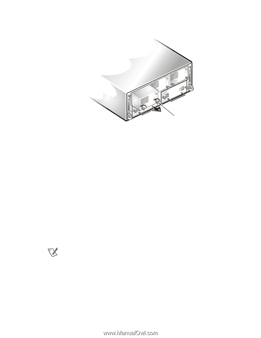
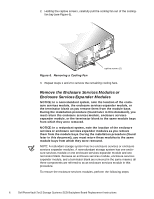
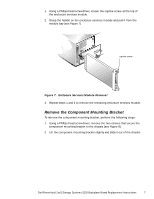
2. Holding the captive screws, carefully pull the cooling fan out of the coolingfan bay (see Figure 6). Figure 6. Removing a Cooling Fan captive screws (2) 3. Repeat steps 1 and 2 to remove the remaining cooling fans. Remove the Enclosure Services Modules or Enclosure Services Expander Modules NOTICE: In a nonredundant system, note the location of the enclosure services module, the enclosure services expander module, or the terminator blank as you remove them from the module bays. During the installation procedure (found later in this document), you must return the enclosure services module, enclosure services expander module, or the terminator blank to the same module bays from which they were removed. NOTICE: In a redundant system, note the location of the enclosure services or enclosure services expander modules as you remove them from the module bays. During the installation procedure (found later in this document), you must return these modules to the same module bays from which they were removed. NOTE: A redundant storage system has two enclosure services or enclosure services expander modules. A nonredundant storage system has one enclosure services module or one enclosure services expander module and one terminator blank. Because an enclosure services module, enclosure services expander module, and a terminator blank are removed in the same manner, all three components are referred to as an enclosure services module in this procedure. To remove the enclosure services modules, perform the following steps: 6 Dell PowerVault 2xxS Storage Systems SCSI Backplane Board Replacement Instructions
-
 1
1 -
 2
2 -
 3
3 -
 4
4 -
 5
5 -
 6
6 -
 7
7 -
 8
8 -
 9
9 -
 10
10 -
 11
11 -
 12
12 -
13
-
14
 |
 |