Dell PowerVault 210S Dell PowerVault 20xS Storage Systems Enclosure Services - Page 5
Wear a wrist grounding strap, and clip it to an unpainted metal surface - will not turn on
 |
View all Dell PowerVault 210S manuals
Add to My Manuals
Save this manual to your list of manuals |
Page 5 highlights
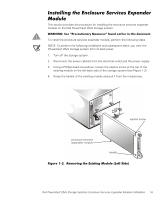
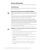
1. Turn off the storage system. 2. Disconnect the storage system from its power source(s). 3. Disconnect any communications cables. 4. Wear a wrist grounding strap, and clip it to an unpainted metal surface, such as a part of the back panel, on the chassis. If a wrist grounding strap is not available, touch the fan guard or some other unpainted metal surface on the back of the chassis to discharge any static charge from your body. NOTES: Two enclosure services expander modules are required for cluster operation. When you configure the enclosure services expander modules using the forced joined mode for cluster operation, the storage system cannot operate in a split-backplane (2 x 4) configuration when two cables are attached. To configure the enclosure services expander modules for cluster operation, perform the following steps: 1. Locate the two-pin jumper labeled "FORCED JOINED JP8" on the enclosure services expander module (see Figure 1-1). The enclosure services expander module is shipped with a jumper plug that is connected to only one pin of the jumper. 2. Move the jumper plug to connect the two pins of the FORCED JOINED JP8 jumper. 3. Repeat steps 1 and 2 for the second enclosure services expander module. 4. Install the two enclosure services expander modules into the PowerVault 20xS storage system. See "Installing the Enclosure Services Expander Module" found later in this document. Dell PowerVault 20xS Storage Systems Enclosure Services Expander Module Installation 1-3
-
 1
1 -
 2
2 -
 3
3 -
 4
4 -
 5
5 -
 6
6 -
 7
7 -
 8
8 -
 9
9 -
 10
10 -
 11
11 -
12
-
13
-
14
-
15
-
16
-
17
-
18
-
19
-
20
-
21
-
22
-
23
-
24
-
25
-
26
-
27
-
28
-
29
-
30
-
31
-
32
-
33
-
34
-
35
-
36
-
37
-
38
-
39
-
40
-
41
-
42
-
43
-
44
-
45
-
46
-
47
-
48
 |
 |