Dell PowerVault 530F Rack Installation Guide - Page 25
Dell PowerVault 530F Manual
 |
View all Dell PowerVault 530F manuals
Add to My Manuals
Save this manual to your list of manuals |
Page 25 highlights
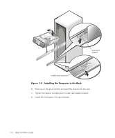
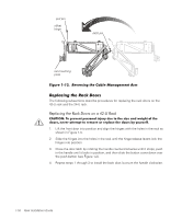
7. At the back of the cabinet, pull back on the mounting-bracket flange until the mounting hooks are located in their respective square holes, and then push down on the mounting-bracket flange until the mounting hooks engage the square holes on the back vertical rail, allowing the push button to pop out and click. 8. Repeat steps 3 through 7 for the remaining slide assembly on the other side of the rack. 1. Pull the two interior slide assemblies out of the rack until they lock in the extended position. 2. Lift the computer into position. 3. Tilt the front of the computer upward while aligning the back shoulder screws on the sides of the computer with the back slots on the slide assemblies (see Figure 1-9). 4. Engage the back shoulder screws in the slot just behind the back (green) latch first, followed by the middle shoulder screw in the slot near the middle (yellow) latch. Finally, engage the front shoulder screw in the front slot. 5. Push the computer inward on the slide assemblies until the middle (yellow) latch clicks into place, locking the slide to the middle shoulder screw (see Figure 1-9). support.dell.com Rack Installation Guide 1-11
-
 1
1 -
2
-
3
-
4
-
5
-
6
-
7
-
8
-
9
-
10
-
11
-
12
-
13
-
14
-
15
-
16
-
17
-
18
-
19
-
 20
20 -
 21
21 -
 22
22 -
 23
23 -
 24
24 -
 25
25 -
 26
26 -
 27
27 -
 28
28 -
 29
29 -
 30
30 -
31
-
32
-
33
-
34
 |
 |
