Dell Precision 400 User's Guide (.pdf) - Page 73
Replacing the Expansion-Card Cage, Rotating the Power Supply Away From the System Boa...
 |
View all Dell Precision 400 manuals
Add to My Manuals
Save this manual to your list of manuals |
Page 73 highlights
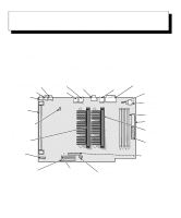
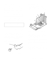
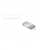
3. Locate the card-cage securing lever (see Figure 7-6). Rotate the lever toward the back of the computer until it stops in an upright position. securing lever card cage Figure 7-6. Removing the ExpansionCard Cage 4. Lift the expansion-card cage up and away from the chassis. Replacing the Expansion-Card Cage Use the following procedure to replace the expansioncard cage: 1. With the securing lever in the upright position, fit the expansion-card cage flush against the left wall of the chassis and lower it into place. 2. Rotate the securing lever toward the front of the chassis, all the way down. Make sure the riser board is fully seated in the RISER connector on the system board. 3. Reconnect any cables you removed in step 2 of the previous procedure, "Removing the ExpansionCard Cage." Rotating the Power Supply Away From the System Board The memory and battery sockets and the power and processor fan connectors lie beneath the power supply. To access any of these features, you can rotate the power supply away from the system board as follows: 1. Remove the computer cover as instructed in "Removing the Computer Cover" found earlier in this chapter. 2. Unplug the alternating current (AC) power cable from the AC power receptacle on the back of the computer (see Figure 7-5). 3. Facing the front of the computer, locate the securing tab (labeled "RELEASE") at the back-left corner of the power supply (see Figure 7-7). Push the tab to the left to disengage the power supply, and rotate the power supply to the right until it stops. The power supply can remain in this vertical position while you work on the system board. To replace the power supply, rotate it back into position, making sure that the securing tab snaps into place. power supply securing tab Figure 7-7. Rotating the Power Supply Working Inside Your Computer 7-5
-
 1
1 -
2
-
3
-
4
-
5
-
6
-
7
-
8
-
9
-
10
-
11
-
12
-
13
-
14
-
15
-
16
-
17
-
18
-
19
-
20
-
21
-
22
-
23
-
24
-
25
-
26
-
27
-
28
-
29
-
30
-
31
-
32
-
33
-
34
-
35
-
36
-
37
-
38
-
39
-
40
-
41
-
42
-
43
-
44
-
45
-
46
-
47
-
48
-
49
-
50
-
51
-
52
-
53
-
54
-
55
-
56
-
57
-
58
-
59
-
60
-
61
-
62
-
63
-
64
-
65
-
66
-
67
-
 68
68 -
 69
69 -
 70
70 -
 71
71 -
 72
72 -
 73
73 -
 74
74 -
 75
75 -
 76
76 -
 77
77 -
 78
78 -
79
-
80
-
81
-
82
-
83
-
84
-
85
-
86
-
87
-
88
-
89
-
90
-
91
-
92
-
93
-
94
-
95
-
96
-
97
-
98
-
99
-
100
-
101
-
102
-
103
-
104
-
105
-
106
-
107
-
108
-
109
-
110
-
111
-
112
-
113
-
114
-
115
-
116
-
117
-
118
-
119
-
120
-
121
-
122
-
123
-
124
-
125
-
126
-
127
-
128
-
129
-
130
-
131
-
132
-
133
-
134
-
135
-
136
-
137
-
138
-
139
-
140
-
141
-
142
-
143
-
144
-
145
-
146
-
147
-
148
-
149
-
150
-
151
-
152
-
153
-
154
-
155
-
156
-
157
-
158
-
159
-
160
-
161
-
162
-
163
-
164
-
165
-
166
-
167
-
168
-
169
-
170
 |
 |
