Dell Studio XPS M1340 Service Manual - Page 13
Graphic Processor Heat Sink/Thermal Fan
 |
View all Dell Studio XPS M1340 manuals
Add to My Manuals
Save this manual to your list of manuals |
Page 13 highlights
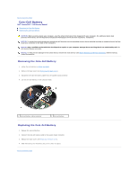
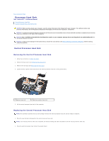
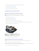
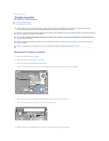
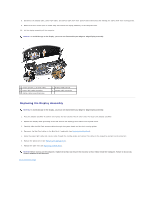
3. Tighten the four captive screws that secure the central processor heat sink to the system board. 4. Replace the rear caps (see Replacing the Rear Caps). 5. Replace the base cover (see Replacing the Base Cover). 6. Slide the battery into the battery bay until it clicks into place. Graphic Processor Heat Sink/Thermal Fan Removing the Graphic Processor Heat Sink/Thermal Fan NOTE: The graphic processor heat sink availability may depend on your system configuration. NOTE: The removal procedure for the thermal fan may differ according to your system configuration. 1. Follow the instructions in Before You Begin. 2. Remove the base cover (see Removing the Base Cover). 3. Remove the rear caps (see Removing the Rear Caps). 4. Remove the central processor heat sink (see Removing the Central Processor Heat Sink). 5. Loosen the two captive screws and remove the other two screws that secure the graphic processor heat sink/thermal fan to the system board. 6. Disconnect the thermal fan cable from the system board connector. 1 fan cable 3 thermal fan 5 captive screws (2) 2 graphic processor heat sink 4 screws (2) 7. Lift the graphic processor heat sink/thermal fan off the computer. Replacing the Graphic Processor Heat Sink/Thermal Fan NOTE: This procedure assumes that you have already removed the graphic processor heat sink/thermal fan and are ready to replace it. 1. Place the new thermal cooling pad on the graphic processor heat sink/thermal fan. NOTE: If the graphic processor heat sink is replaced, the thermal cooling pad will be attached to the new graphic processor heat sink. Use the thermal cooling pad provided in the kit on the central processor heat sink and graphic processor heat sink. 2. Place the graphic processor heat sink/thermal fan on the system board.
-
 1
1 -
2
-
3
-
4
-
5
-
6
-
7
-
 8
8 -
 9
9 -
 10
10 -
 11
11 -
 12
12 -
 13
13 -
 14
14 -
 15
15 -
 16
16 -
 17
17 -
 18
18 -
19
-
20
-
21
-
22
-
23
-
24
-
25
-
26
-
27
-
28
-
29
-
30
-
31
-
32
-
33
-
34
-
35
-
36
-
37
-
38
-
39
 |
 |