Dell Vostro 1000 Service Manual
Dell Vostro 1000 Manual
 |
View all Dell Vostro 1000 manuals
Add to My Manuals
Save this manual to your list of manuals |
Dell Vostro 1000 manual content summary:
- Dell Vostro 1000 | Service Manual - Page 1
/Dell Vostro™ 1000 Service Manual Before You Begin Optical Drive Hard Drive Memory Module(s) Modem Mini-Card Keyboard Hinge Cover Display Assembly Palm Rest Coin-Cell Battery Speakers Processor Thermal-Cooling Assembly Processor Module Fan ExpressCard/Hard-Drive Bay Assembly System Board Battery - Dell Vostro 1000 | Service Manual - Page 2
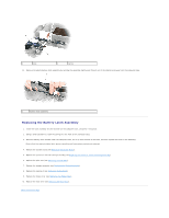
to Contents Page Battery Latch Assembly Dell™ Latitude™ 131L/ Dell Vostro™ 1000 Service Manual Removing the Battery Latch Assembly Replacing the Battery Latch Assembly CAUTION: Before you begin the following procedure, follow the safety instructions in the Product Information Guide. NOTICE: To avoid - Dell Vostro 1000 | Service Manual - Page 3
palm rest (see Replacing the Palm Rest). 7. Replace the display assembly (see Replacing the Display Assembly). 8. Replace the keyboard (see Replacing the Keyboard). 9. Replace the hinge cover (see Replacing the Hinge Cover). 10. Replace the hard drive (see Replacing the Hard Drive). Back to Contents - Dell Vostro 1000 | Service Manual - Page 4
Begin Dell™ Latitude™ 131L/ Dell Vostro™ 1000 Service Manual Recommended Tools driver l Flash BIOS update program CD Turning Off Your Computer NOTICE: To avoid losing data, save and close any open files and exit any open programs before you turn off your computer. 1. Shut down the operating system - Dell Vostro 1000 | Service Manual - Page 5
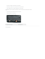
computer. 4. Disconnect your computer and all attached devices from their electrical outlets. 5. Close the display and turn the computer upside-down on a flat work surface. NOTICE: To help prevent damage to the system board, remove the main battery before working inside the computer. 6. Slide the - Dell Vostro 1000 | Service Manual - Page 6
Back to Contents Page Flashing the BIOS Dell™ Latitude™ 131L/ Dell Vostro™ 1000 Service Manual 1. Ensure that the AC adapter is plugged in and that the main battery is installed properly. NOTE: If you use a BIOS update program CD to flash the BIOS, set up the computer to boot from a CD before - Dell Vostro 1000 | Service Manual - Page 7
Back to Contents Page Bluetooth® Card Dell™ Latitude™ 131L/ Dell Vostro™ 1000 Service Manual Removing a Bluetooth Card Replacing a Bluetooth Card CAUTION: Before you begin any of the procedures in this section, follow the safety instructions in the Product Information Guide. NOTICE: To avoid - Dell Vostro 1000 | Service Manual - Page 8
/Hard-Drive Bay Assembly Dell™ Latitude™ 131L/ Dell Vostro™ 1000 Service Manual Removing the ExpressCard/Hard-Drive Bay Assembly Replacing the ExpressCard/Hard-Drive Bay Assembly CAUTION: Before you begin the following procedure, follow the safety instructions in the Product Information Guide - Dell Vostro 1000 | Service Manual - Page 9
Back to Contents Page - Dell Vostro 1000 | Service Manual - Page 10
™ 131L/ Dell Vostro™ 1000 Service Manual Removing a Mini-Card Replacing a Mini-Card If you ordered a Mini-Card with your computer, the card is already installed. CAUTION: Before you begin any of the procedures in this section, follow the safety instructions in the Product Information Guide. NOTICE - Dell Vostro 1000 | Service Manual - Page 11
the Mini-Card connector into the system board connector at a 45-degree angle. 2. Press the other end of the Mini-Card into the securing tabs until the card clicks into place. 3. Connect the black antenna cable to the connector labeled with a black triangle, and connect the white antenna cable to - Dell Vostro 1000 | Service Manual - Page 12
to Contents Page Coin-Cell Battery Dell™ Latitude™ 131L/ Dell Vostro™ 1000 Service Manual Removing the Coin-Cell Battery Replacing the Coin-Cell Battery CAUTION: Before you begin the following procedure, follow the safety instructions in the Product Information Guide. NOTICE: To avoid electrostatic - Dell Vostro 1000 | Service Manual - Page 13
-Cooling Assembly Dell™ Latitude™ 131L/ Dell Vostro™ 1000 Service Manual Removing the Processor Thermal-Cooling Assembly Replacing the Processor Thermal-Cooling Assembly CAUTION: Before you begin the following procedure, follow the safety instructions in the Product Information Guide. NOTICE: To - Dell Vostro 1000 | Service Manual - Page 14
- Dell Vostro 1000 | Service Manual - Page 15
Page Display Assembly Dell™ Latitude™ 131L/ Dell Vostro™ 1000 Service Manual Removing the Display Assembly Replacing the Display Assembly Display Bezel Display Panel Display Latch CAUTION: Before you begin the following procedure, follow the safety instructions in the Product Information Guide - Dell Vostro 1000 | Service Manual - Page 16
clear of the computer base before replacing the display. 1. Place the display onto the computer base. 2. Replace the two M2.5 x 5-mm screws in the display hinge. 3. Securely route the display cable under the tabs in the cable channel. 4. Connect the display cable to the system board and tighten the - Dell Vostro 1000 | Service Manual - Page 17
to the system board, you must remove the main battery (see Before Working Inside Your Computer) before you begin working inside the computer. Removing the Display Bezel 1. Follow the instructions in Before You Begin. 2. Remove the display assembly (see Removing the Display Assembly). 3. Remove - Dell Vostro 1000 | Service Manual - Page 18
system board, you must remove the main battery (see Before Working Inside Your Computer) before you begin working inside the computer. Removing the Display Panel 1. Follow the instructions in Before You Begin. 2. Remove the display assembly (see Removing the Display Assembly). 3. Remove the display - Dell Vostro 1000 | Service Manual - Page 19
(four on each side) in order around the display panel. 5. Replace the display bezel (see Replacing the Display Bezel). Display Latch CAUTION: Before you begin the following procedure, follow the safety instructions in the Product Information Guide. NOTICE: To avoid electrostatic discharge, ground - Dell Vostro 1000 | Service Manual - Page 20
1. Replace the spring that attaches the latch to the display panel. 2. Align the latch with the display panel and slide the latch to the left to secure it into place. Back to Contents Page - Dell Vostro 1000 | Service Manual - Page 21
Back to Contents Page Fan Dell™ Latitude™ 131L/ Dell Vostro™ 1000 Service Manual Removing a Fan Replacing a Fan CAUTION: Before you begin the following procedure, follow the safety instructions in the Product Information Guide. NOTICE: To avoid electrostatic discharge, ground yourself by using a - Dell Vostro 1000 | Service Manual - Page 22
5. Replace the keyboard (see Replacing the Keyboard). 6. Replace the hinge cover (see Replacing the Hinge Cover). Back to Contents Page - Dell Vostro 1000 | Service Manual - Page 23
Dell HTML Functional Test Report Version 14 Last Revised Date: August 2006 Overview Scope Testing includes: l Verifying that the HTML files display and function correctly under Internet HTTP-EQUIV="Content-Type" content="text/html; charset=windows-1253"> Hebrew - Dell Vostro 1000 | Service Manual - Page 24
text/html; charset=windows-874"> Turkish not hard-coded X 9. Manually check all links in Internet Explorer. factory, verify that a title.txt file is part of the directory, and is in the correct language (the title.txt file is not needed for docs that are Web posted only, such as Service Manuals - Dell Vostro 1000 | Service Manual - Page 25
/ Dell Vostro™ 1000 Service Manual Removing the Hard Drive Replacing the Hard Drive CAUTION: If you remove the hard drive from the computer when the drive is hot, do not touch the metal housing of the hard drive. CAUTION: Before you begin the following procedure, follow the safety instructions in - Dell Vostro 1000 | Service Manual - Page 26
Back to Contents Page - Dell Vostro 1000 | Service Manual - Page 27
Back to Contents Page Hinge Cover Dell™ Latitude™ 131L/ Dell Vostro™ 1000 Service Manual Removing the Hinge Cover Replacing the Hinge Cover CAUTION: Before you begin the following procedure, follow the safety instructions in the Product Information Guide. NOTICE: To avoid electrostatic discharge, - Dell Vostro 1000 | Service Manual - Page 28
Back to Contents Page Keyboard Dell™ Latitude™ 131L/ Dell Vostro™ 1000 Service Manual Removing the Keyboard Replacing the Keyboard CAUTION: Before you begin the following procedure, follow the safety instructions in the Product Information Guide. NOTICE: To avoid electrostatic discharge, ground - Dell Vostro 1000 | Service Manual - Page 29
3. Press lightly on the top edges of the keyboard to snap it into place. 4. Replace the two M2.5 x 5-mm screws at the top of the keyboard. Back to Contents Page - Dell Vostro 1000 | Service Manual - Page 30
Back to Contents Page Memory Module(s) Dell™ Latitude™ 131L/ Dell Vostro™ 1000 Service Manual Removing the Memory Module(s) Replacing the Memory Module(s) CAUTION: Before you begin the following procedure, follow the safety instructions in the Product Information Guide. NOTICE: To prevent static - Dell Vostro 1000 | Service Manual - Page 31
may damage your computer. 4. Insert the battery into the battery bay, or connect the AC adapter to your computer and an electrical outlet. 5. Turn on the computer. As the computer boots, it detects the additional memory and automatically updates the system configuration information. Back to Contents - Dell Vostro 1000 | Service Manual - Page 32
Back to Contents Page Modem Dell™ Latitude™ 131L/ Dell Vostro™ 1000 Service Manual Removing the Modem Replacing the Modem CAUTION: Before you begin the following procedure, follow the safety instructions in the Product Information Guide. NOTICE: To avoid electrostatic discharge, ground yourself by - Dell Vostro 1000 | Service Manual - Page 33
NOTICE: Do not disconnect the modem cable from the system board. 5. Disconnect the modem cable from the modem. Replacing the Modem 1. Connect the modem cable to the modem. NOTICE: Ensure that the modem cable is routed correctly when you replace the modem. 2. Align the connector on the bottom of the - Dell Vostro 1000 | Service Manual - Page 34
Drive Dell™ Latitude™ 131L/ Dell Vostro™ 1000 Service Manual Removing an Optical Drive Replacing an Optical Drive Your computer ships with a fixed optical drive installed. CAUTION: Before you begin any of the procedures in this section, follow the safety instructions in the Product Information Guide - Dell Vostro 1000 | Service Manual - Page 35
Back to Contents Page Palm Rest Dell™ Latitude™ 131L/ Dell Vostro™ 1000 Service Manual Removing the Palm Rest Replacing the Palm Rest CAUTION: Before you begin the following procedure, follow the safety instructions in the Product Information Guide. NOTICE: To avoid electrostatic discharge, ground - Dell Vostro 1000 | Service Manual - Page 36
of the computer. 5. Replace the optical drive (see Replacing an Optical Drive). 6. Turn the computer top-side up and replace the display assembly (see Replacing the Display Assembly). 7. Replace the keyboard (see Replacing the Keyboard). 8. Replace the hinge cover (see Replacing the Hinge Cover - Dell Vostro 1000 | Service Manual - Page 37
Back to Contents Page Pin Assignments for I/O Connectors Dell™ Latitude™ 131L/ Dell Vostro™ 1000 Service Manual USB Connector Video Connector USB Connector Pin Signal 1 USB5V+ 2 USBP- 3 USBP+ 4 GND Video Connector Pin Signal Pin Signal 1 CRT_R 9 5V+ 2 CRT_G 10 GND 3 CRT_B 11 - Dell Vostro 1000 | Service Manual - Page 38
to Contents Page Processor Module Dell™ Latitude™ 131L/ Dell Vostro™ 1000 Service Manual Removing the Processor Module Replacing the Processor Module CAUTION: Before you begin the following procedure, follow the safety instructions in the Product Information Guide. NOTICE: To avoid electrostatic - Dell Vostro 1000 | Service Manual - Page 39
result in an intermittent connection or permanent damage to the system board. 3. Replace the palm rest (see Replacing the Palm Rest). 4. Replace the display assembly (see Replacing the Display Assembly). 5. Replace the keyboard (see Replacing the Keyboard). 6. Replace the hinge cover (see Replacing - Dell Vostro 1000 | Service Manual - Page 40
Back to Contents Page Speakers Dell™ Latitude™ 131L/ Dell Vostro™ 1000 Service Manual Removing the Speakers Replacing the Speakers CAUTION: Before you begin the following procedure, follow the safety instructions in the Product Information Guide. NOTICE: To avoid electrostatic discharge, ground - Dell Vostro 1000 | Service Manual - Page 41
the Speakers 1. Route the speaker cable back through the routing clips and connect the speaker cable connector to the system board. 2. Align the speakers on the screw holes for securing the speakers to the computer base. 3. Replace the two M2.5 x 5-mm screws to secure the speakers in place (one - Dell Vostro 1000 | Service Manual - Page 42
Back to Contents Page System Board Dell™ Latitude™ 131L/ Dell Vostro™ 1000 Service Manual Removing the System Board Replacing the System Board CAUTION: Before you begin the following procedure, follow the safety instructions in the Product Information Guide. NOTICE: To avoid electrostatic discharge, - Dell Vostro 1000 | Service Manual - Page 43
-drive bay assembly (see Replacing the ExpressCard/Hard-Drive Bay Assembly). 5. Replace the processor (see Replacing the Processor Module). 6. Replace the processor thermal-cooling assembly (see Replacing the Processor Thermal-Cooling Assembly). 7. Replace the fan (see Replacing a Fan). 8. Replace - Dell Vostro 1000 | Service Manual - Page 44
BIOS update program CD that accompanied the replacement system board into the optical drive. Follow the instructions that appear on the screen. See "Flashing the Bios" for further information. 20. Enter the system setup program to update the BIOS on the new system board with the computer Service - Dell Vostro 1000 | Service Manual - Page 45
Contents Page Dell™ Latitude™ 131L/ Dell Vostro™ 1000 Service Manual NOTE: A NOTE indicates important information that helps you make better use of your computer. NOTICE: A NOTICE indicates either potential damage to hardware or loss of data and tells you how to avoid the problem. CAUTION: A CAUTION
-
 1
1 -
 2
2 -
 3
3 -
 4
4 -
 5
5 -
 6
6 -
 7
7 -
8
-
9
-
10
-
11
-
12
-
13
-
14
-
15
-
16
-
17
-
18
-
19
-
20
-
21
-
22
-
23
-
24
-
25
-
26
-
27
-
28
-
29
-
30
-
31
-
32
-
33
-
34
-
35
-
36
-
37
-
38
-
39
-
40
-
41
-
42
-
43
-
44
-
45
 |
 |

Dell™ Latitude™ 131L/Dell Vostro™ 1000 Service Manual
Notes, Notices, and Cautions
Abbreviations and Acronyms
For a complete list of abbreviations and acronyms, see "Glossary" in the
User's Guide
.
If you purchased a Dell n Series computer, any references in this document to Microsoft
®
Windows
®
operating systems are not applicable.
Information in this document is subject to change without notice.
© 2007 Dell Inc. All rights reserved.
Reproduction in any manner whatsoever without the written permission of Dell Inc.
is strictly forbidden.
Trademarks used in this text:
Dell
, the
DELL
logo,
Vostro
, and
Latitude
are trademarks of Dell Inc.;
Microsoft
and
Windows
are registered trademarks of Microsoft Corporation.
Other trademarks and trade names may be used in this document to refer to either the entities claiming the marks and names or their products. Dell Inc. disclaims any
proprietary interest in trademarks and trade names other than its own.
Model PP23LB
July 2007 Rev. A01
Before You Begin
Coin
-
Cell Battery
Optical Drive
Speakers
Hard Drive
Processor Thermal
-
Cooling Assembly
Memory Module(s)
Processor Module
Modem
Fan
Mini
-
Card
ExpressCard/Hard
-
Drive Bay Assembly
Keyboard
System Board
Hinge Cover
Battery Latch Assembly
Display Assembly
Flashing the BIOS
Palm Rest
Pin Assignments for I/O Connectors
NOTE:
A NOTE indicates important information that helps you make better use of your computer.
CAUTION:
A CAUTION indicates a potential for property damage, personal injury, or death.
NOTE:
The color of your computer may vary from what is shown in this document.