Dell Vostro 1000 Service Manual - Page 8
ExpressCard/Hard-Drive Bay Assembly - hard drive replacement
 |
View all Dell Vostro 1000 manuals
Add to My Manuals
Save this manual to your list of manuals |
Page 8 highlights
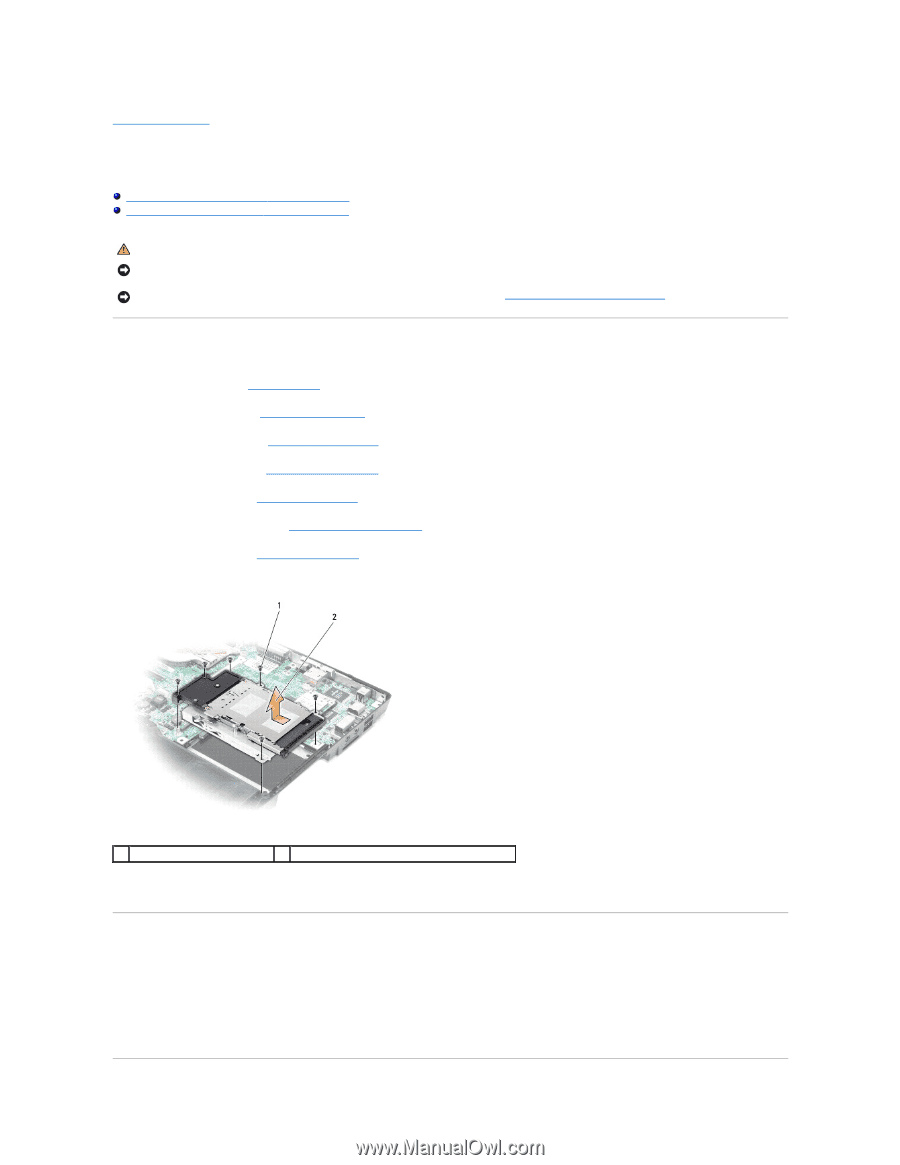
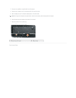
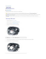
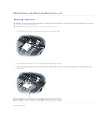
Back to Contents Page ExpressCard/Hard-Drive Bay Assembly Dell™ Latitude™ 131L/ Dell Vostro™ 1000 Service Manual Removing the ExpressCard/Hard-Drive Bay Assembly Replacing the ExpressCard/Hard-Drive Bay Assembly CAUTION: Before you begin the following procedure, follow the safety instructions in the Product Information Guide. NOTICE: To avoid electrostatic discharge, ground yourself by using a wrist grounding strap or by periodically touching an unpainted metal surface (such as the back panel) on the computer. NOTICE: To help prevent damage to the system board, remove the main battery (see Before Working Inside Your Computer) before working inside the computer. Removing the ExpressCard/Hard-Drive Bay Assembly 1. Follow the instructions in Before You Begin. 2. Remove the hard drive (see Removing the Hard Drive). 3. Remove the optical drive (see Removing an Optical Drive). 4. Remove the hinge cover (see Removing the Hinge Cover). 5. Remove the keyboard (see Removing the Keyboard). 6. Remove the display assembly (see Removing the Display Assembly). 7. Remove the palm rest (see Removing the Palm Rest). 8. Remove the six M2.5x 5-mm screws from the ExpressCard/hard-drive bay assembly. 1 M2.5 x 5-mm screws (6) 2 ExpressCard/hard-drive bay assembly 9. Remove the assembly from the system board. Replacing the ExpressCard/Hard-Drive Bay Assembly 1. At a 45-degree angle, insert the end of the ExpressCard/hard-drive bay assembly into its access hole on the side of the computer base. 2. Lower the assembly aligning the screw holes on the assembly with the holes on the system board. 3. Replace the six M2.5x 5-mm screws from the assembly.
-
 1
1 -
2
-
 3
3 -
 4
4 -
 5
5 -
 6
6 -
 7
7 -
 8
8 -
 9
9 -
 10
10 -
 11
11 -
 12
12 -
 13
13 -
14
-
15
-
16
-
17
-
18
-
19
-
20
-
21
-
22
-
23
-
24
-
25
-
26
-
27
-
28
-
29
-
30
-
31
-
32
-
33
-
34
-
35
-
36
-
37
-
38
-
39
-
40
-
41
-
42
-
43
-
44
-
45
 |
 |