Dell Vostro 1000 Service Manual - Page 18
Display Panel - inverter replacement
 |
View all Dell Vostro 1000 manuals
Add to My Manuals
Save this manual to your list of manuals |
Page 18 highlights
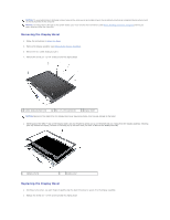
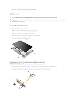
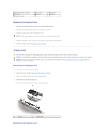
3. Replace the six rubber display bumpers around the display bezel. Display Panel CAUTION: Before you begin the following procedure, follow the safety instructions in the Product Information Guide. NOTICE: To avoid electrostatic discharge, ground yourself by using a wrist grounding strap or by touching an unpainted metal surface on the computer. NOTICE: To help prevent damage to the system board, you must remove the main battery (see Before Working Inside Your Computer) before you begin working inside the computer. Removing the Display Panel 1. Follow the instructions in Before You Begin. 2. Remove the display assembly (see Removing the Display Assembly). 3. Remove the display bezel (see Removing the Display Bezel). 4. Remove the eight M2 x 3-mm screws (four on each side of the display panel). 5. Lift the display panel out of the display back cover. 1 display panel 4 grounding wire and captive screw 2 display back cover 3 M2 x 3-mm screws (8) 6. Press in both sides of the top flex-cable connector, and pull the top flex-cable connector away from the display connector. 7. Pull straight up on the pull-tab to disconnect the bottom flex-cable connector from the inverter connector.
-
 1
1 -
2
-
3
-
4
-
5
-
6
-
7
-
8
-
9
-
10
-
11
-
12
-
 13
13 -
 14
14 -
 15
15 -
 16
16 -
 17
17 -
 18
18 -
 19
19 -
 20
20 -
 21
21 -
 22
22 -
 23
23 -
24
-
25
-
26
-
27
-
28
-
29
-
30
-
31
-
32
-
33
-
34
-
35
-
36
-
37
-
38
-
39
-
40
-
41
-
42
-
43
-
44
-
45
 |
 |
