Dell Vostro 220 Service Manual - Page 119
System Board, Remove the System Board - dvd drive not working
 |
UPC - 884116011958
View all Dell Vostro 220 manuals
Add to My Manuals
Save this manual to your list of manuals |
Page 119 highlights
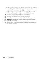
System Board CAUTION: Before working inside your computer, read the safety information that shipped with your computer. For additional safety best practices information, see the Regulatory Compliance Homepage at www.dell.com/regulatory_compliance. CAUTION: To guard against likelihood of electric shock, laceration by moving fan blades, or other unexpected injuries, always unplug your computer from the electrical outlet before removing the cover. NOTICE: The procedure for removing and replacing the system board is identical (except where noted) for the Vostro 420, Vostro 220, and Vostro 220s computers; the illustration provided is for example only and may not represent your particular computer precisely. Remove the System Board 1 Follow the procedures in "Before Working on Your Computer" on page 35. 2 Remove the computer cover (see "Removing the Computer Cover" on page 47). 3 For the Vostro 220s: a Remove the chassis support bracket (see "Removing the Chassis Support Bracket" on page 55). b Slide the optical drive forward far enough to gain access to the PWR1 connector on the system board. 4 Remove all expansion cards (see "Removing a PCI or PCI Express Card" on page 59). Store them temporarily in separate antistatic packaging to prevent damage from discharge of static electricity. 5 Disconnect all the CD/DVD/hard drive data cables from the system board. 6 Disconnect all front panel cables from the system board. 7 Disconnect the DC power cables from the system board. 8 If the system board is being replaced with another system board: a Remove the processor heat sink/fan assembly (see "Removing the Processor Heat Sink/Fan Assembly" on page 99). System Board 119
-
 1
1 -
2
-
3
-
4
-
5
-
6
-
7
-
8
-
9
-
10
-
11
-
12
-
13
-
14
-
15
-
16
-
17
-
18
-
19
-
20
-
21
-
22
-
23
-
24
-
25
-
26
-
27
-
28
-
29
-
30
-
31
-
32
-
33
-
34
-
35
-
36
-
37
-
38
-
39
-
40
-
41
-
42
-
43
-
44
-
45
-
46
-
47
-
48
-
49
-
50
-
51
-
52
-
53
-
54
-
55
-
56
-
57
-
58
-
59
-
60
-
61
-
62
-
63
-
64
-
65
-
66
-
67
-
68
-
69
-
70
-
71
-
72
-
73
-
74
-
75
-
76
-
77
-
78
-
79
-
80
-
81
-
82
-
83
-
84
-
85
-
86
-
87
-
88
-
89
-
90
-
91
-
92
-
93
-
94
-
95
-
96
-
97
-
98
-
99
-
100
-
101
-
102
-
103
-
104
-
105
-
106
-
107
-
108
-
109
-
110
-
111
-
112
-
113
-
 114
114 -
 115
115 -
 116
116 -
 117
117 -
 118
118 -
 119
119 -
 120
120 -
 121
121 -
 122
122 -
 123
123 -
 124
124 -
125
-
126
-
127
-
128
-
129
-
130
-
131
-
132
-
133
-
134
-
135
-
136
-
137
-
138
 |
 |