Dell Vostro 220 Service Manual - Page 89
I/O Panel, Removing the I/O Panel
 |
UPC - 884116011958
View all Dell Vostro 220 manuals
Add to My Manuals
Save this manual to your list of manuals |
Page 89 highlights
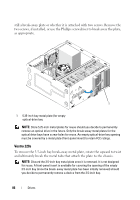
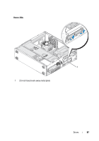
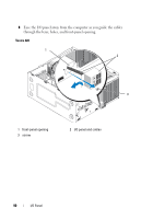
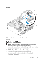
I/O Panel CAUTION: Before working inside your computer, read the safety information that shipped with your computer. For additional safety best practices information, see the Regulatory Compliance Homepage at www.dell.com/regulatory_compliance. CAUTION: To guard against electrical shock, always unplug your computer from the electrical outlet before removing the cover. NOTICE: The procedure for removing and replacing the I/O panel is identical (except where noted) for the Vostro 420, Vostro 220, and Vostro 220s computers; the illustrations provided are for example only and may not represent your particular computer precisely. Removing the I/O Panel NOTE: Note the routing of all cables as you remove them so that you can reroute them correctly when installing the new I/O panel. 1 Follow the procedures in "Before Working on Your Computer" on page 35. 2 Remove the computer cover (see "Removing the Computer Cover" on page 47). 3 Remove the bezel (see "Removing the Bezel" on page 51). 4 Disconnect the I/O panel cables from the system board. 5 For the Vostro 220s: a Remove the chassis support bracket (see "Removing the Chassis Support Bracket" on page 55). b Remove any hard drives from the hard drive cage (see "Removing a Hard Drive" on page 65). 6 Disengage the cables from the metal clip(s), if present, that secure(s) the cables along the inside of the chassis. 7 Remove the screw that secures the I/O panel to the front panel. NOTICE: When sliding the I/O panel out of the computer, guide the cables carefully through the bays, holes, and front-panel opening to prevent damage to the cable connectors and the cable routing clip(s) (if present). I/O Panel 89
-
 1
1 -
2
-
3
-
4
-
5
-
6
-
7
-
8
-
9
-
10
-
11
-
12
-
13
-
14
-
15
-
16
-
17
-
18
-
19
-
20
-
21
-
22
-
23
-
24
-
25
-
26
-
27
-
28
-
29
-
30
-
31
-
32
-
33
-
34
-
35
-
36
-
37
-
38
-
39
-
40
-
41
-
42
-
43
-
44
-
45
-
46
-
47
-
48
-
49
-
50
-
51
-
52
-
53
-
54
-
55
-
56
-
57
-
58
-
59
-
60
-
61
-
62
-
63
-
64
-
65
-
66
-
67
-
68
-
69
-
70
-
71
-
72
-
73
-
74
-
75
-
76
-
77
-
78
-
79
-
80
-
81
-
82
-
83
-
 84
84 -
 85
85 -
 86
86 -
 87
87 -
 88
88 -
 89
89 -
 90
90 -
 91
91 -
 92
92 -
 93
93 -
 94
94 -
95
-
96
-
97
-
98
-
99
-
100
-
101
-
102
-
103
-
104
-
105
-
106
-
107
-
108
-
109
-
110
-
111
-
112
-
113
-
114
-
115
-
116
-
117
-
118
-
119
-
120
-
121
-
122
-
123
-
124
-
125
-
126
-
127
-
128
-
129
-
130
-
131
-
132
-
133
-
134
-
135
-
136
-
137
-
138
 |
 |