Dell Vostro 24 5450 Dell Vostro 245450 Owners Manual - Page 22
System Board Layout, USB 3.0 connector
 |
View all Dell Vostro 24 5450 manuals
Add to My Manuals
Save this manual to your list of manuals |
Page 22 highlights
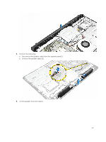
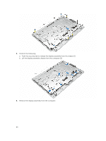
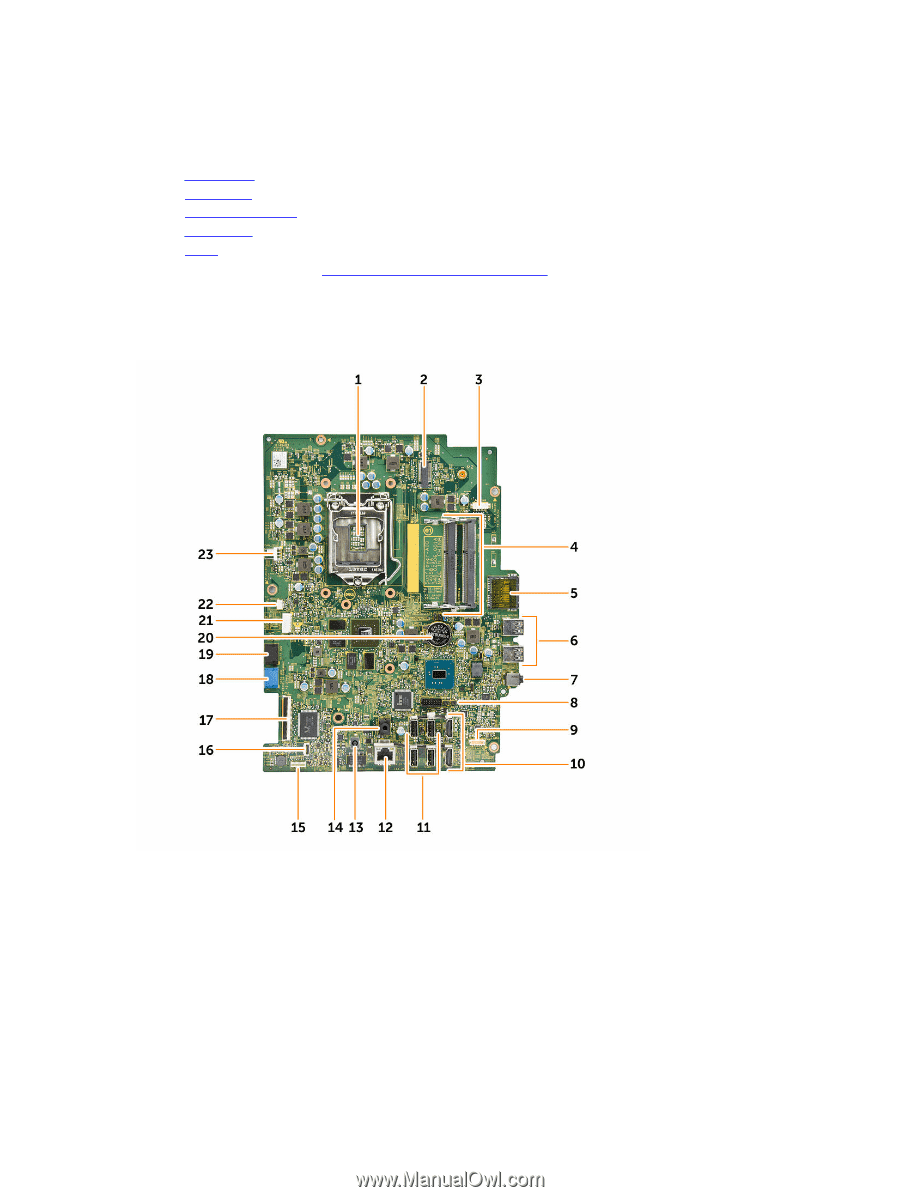
e. power-switch cable f. speaker cable 4. Install: a. WLAN card b. stand cage c. heatsink assembly d. back cover e. stand 5. Follow the procedures in After Working Inside Your Computer. System Board Layout The following image displays the system board layout of the computer. 1. Processor connector 3. Camera connector 5. SD-Card connector 7. Audio-in connector 9. Speaker connector 11. USB 2.0 connector 22 2. WLAN connector 4. Memory module 6. USB 3.0 connector 8. Jumper connector 10. HDMI connector 12. Network connector
-
 1
1 -
2
-
3
-
4
-
5
-
6
-
7
-
8
-
9
-
10
-
11
-
12
-
13
-
14
-
15
-
16
-
 17
17 -
 18
18 -
 19
19 -
 20
20 -
 21
21 -
 22
22 -
 23
23 -
 24
24 -
 25
25 -
 26
26 -
 27
27 -
28
-
29
-
30
-
31
-
32
-
33
-
34
-
35
-
36
-
37
-
38
 |
 |
e.
power-switch cable
f.
speaker cable
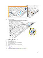
4.
Install:
a.
WLAN card
b.
stand cage
c.
heatsink assembly
d.
back cover
e.
stand
5.
Follow the procedures in
After Working Inside Your Computer
.
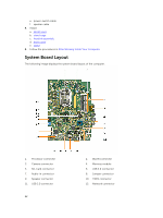
System Board Layout
The following image displays the system board layout of the computer.
1.
Processor connector
2.
WLAN connector
3.
Camera connector
4.
Memory module
5.
SD-Card connector
6.
USB 3.0 connector
7.
Audio-in connector
8.
Jumper connector
9.
Speaker connector
10.
HDMI connector
11.
USB 2.0 connector
12.
Network connector
22