Dell Vostro 24 5450 Dell Vostro 245450 Owners Manual - Page 23
Removing the Display Assembly, SATA connector Optional
 |
View all Dell Vostro 24 5450 manuals
Add to My Manuals
Save this manual to your list of manuals |
Page 23 highlights
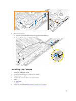
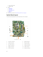
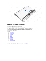
13. DC-in connector 15. Convertor-board connector 17. Display-assembly connector 19. Optical-drive connector 21. SATA connector (Optional) 23. System fan connector 14. Audio-out connector 16. Power connector 18. Hard-drive connector 20. Coin-cell battery 22. Touch connector (Optional) Removing the Display Assembly 1. Follow the procedures in Before Working Inside Your Computer. 2. Remove: a. stand b. back cover c. heatsink assembly d. stand cage e. WLAN card f. hard drive g. speakers h. camera i. system fan j. system board k. power switch 3. Perform the following: a. Unroute the camera, hard drive, convertor board cables [1.2.3]. b. Disconnect the power cable [4]. 4. Remove the screws that secure the display assembly to the chassis. 23
-
 1
1 -
2
-
3
-
4
-
5
-
6
-
7
-
8
-
9
-
10
-
11
-
12
-
13
-
14
-
15
-
16
-
17
-
 18
18 -
 19
19 -
 20
20 -
 21
21 -
 22
22 -
 23
23 -
 24
24 -
 25
25 -
 26
26 -
 27
27 -
 28
28 -
29
-
30
-
31
-
32
-
33
-
34
-
35
-
36
-
37
-
38
 |
 |

13.
DC-in connector
14.
Audio-out connector
15.
Convertor-board connector
16.
Power connector
17.
Display-assembly connector
18.
Hard-drive connector
19.
Optical-drive connector
20.
Coin-cell battery
21.
SATA connector (Optional)
22.
Touch connector (Optional)
23.
System fan connector
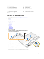
Removing the Display Assembly
1.
Follow the procedures in
Before Working Inside Your Computer
.
2.
Remove:
a.
stand
b.
back cover
c.
heatsink assembly
d.
stand cage
e.
WLAN card
f.
hard drive
g.
speakers
h.
camera
i.
system fan
j.
system board
k.
power switch
3.
Perform the following:
a.
Unroute the camera, hard drive, convertor board cables [1.2.3].
b.
Disconnect the power cable [4].
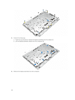
4.
Remove the screws that secure the display assembly to the chassis.
23