Dell Vostro 420 Service Manual - Page 34
Replacing the I/O Panel
 |
UPC - 683728233853
View all Dell Vostro 420 manuals
Add to My Manuals
Save this manual to your list of manuals |
Page 34 highlights
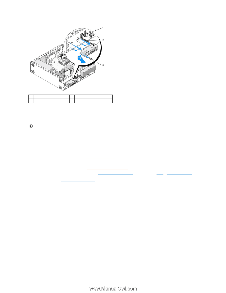
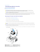
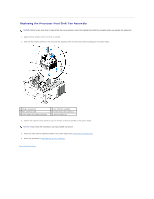
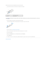
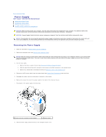
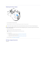
1 front-panel opening 3 screw 2 I/O panel and cables Replacing the I/O Panel NOTICE: Take care not to damage the cable connectors and the cable routing clip(s) (if present) when sliding the I/O panel into the computer. 1. Route the I/O panel cables into the chassis through the I/O panel opening, and guide them through the various holes and bays. 2. Slide the I/O panel cables into the cable clip(s) (if present). 3. Replace and tighten the screw that secures the I/O panel. 4. Reconnect the cables to the system board (see System Board Components). 5. For the Vostro 220s: a. Replace the chassis support bracket (see Replacing the Chassis Support Bracket). b. Replace any hard drives in the hard drive cage (see Replacing or Adding a Hard Drive) that you removed in step 5 of Removing the I/O Panel. 6. Follow the procedure in After Working on Your Computer. Back to Contents Page
-
 1
1 -
2
-
3
-
4
-
5
-
6
-
7
-
8
-
9
-
10
-
11
-
12
-
13
-
14
-
15
-
16
-
17
-
18
-
19
-
20
-
21
-
22
-
23
-
24
-
25
-
26
-
27
-
28
-
 29
29 -
 30
30 -
 31
31 -
 32
32 -
 33
33 -
 34
34 -
 35
35 -
 36
36 -
 37
37 -
 38
38 -
 39
39 -
40
-
41
-
42
-
43
-
44
-
45
-
46
-
47
-
48
-
49
-
50
-
51
-
52
-
53
-
54
-
55
-
56
-
57
-
58
-
59
-
60
-
61
-
62
-
63
-
64
-
65
-
66
-
67
-
68
-
69
-
70
 |
 |