Dell Vostro 5301 Service Manual
Dell Vostro 5301 Manual
 |
View all Dell Vostro 5301 manuals
Add to My Manuals
Save this manual to your list of manuals |
Dell Vostro 5301 manual content summary:
- Dell Vostro 5301 | Service Manual - Page 1
Vostro 5301 Service Manual Regulatory Model: P121G Regulatory Type: P121G002 October 2020 Rev. A00 - Dell Vostro 5301 | Service Manual - Page 2
of data and tells you how to avoid the problem. WARNING: A WARNING indicates a potential for property damage, personal injury, or death. © 2020 Dell Inc. or its subsidiaries. All rights reserved. Dell, EMC, and other trademarks are trademarks of Dell Inc. or its subsidiaries. Other trademarks may be - Dell Vostro 5301 | Service Manual - Page 3
of data and tells you how to avoid the problem. WARNING: A WARNING indicates a potential for property damage, personal injury, or death. © 2020 Dell Inc. or its subsidiaries. All rights reserved. Dell, EMC, and other trademarks are trademarks of Dell Inc. or its subsidiaries. Other trademarks may be - Dell Vostro 5301 | Service Manual - Page 4
1: Working on your computer 6 Safety instructions...6 Before working inside your computer...6 Safety precautions...7 Electrostatic discharge-ESD protection...7 ESD field service kit ...8 After working inside your computer...9 Chapter 2: Major components of Vostro 5301 10 Chapter 3: Disassembly and - Dell Vostro 5301 | Service Manual - Page 5
...53 Removing the power button with fingerprint reader 53 Installing the power button with fingerprint reader 54 Chapter 4: Troubleshooting...56 Dell SupportAssist Pre-boot System Performance Check diagnostics 56 Running the SupportAssist Pre-Boot System Performance Check 56 Validation Tools - Dell Vostro 5301 | Service Manual - Page 6
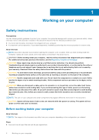
only perform troubleshooting and simple repairs as authorized in your product documentation, or as directed by the online or telephone service and support team. Damage due to servicing that is not authorized by Dell is not covered by your warranty. Read and follow the safety instructions that came - Dell Vostro 5301 | Service Manual - Page 7
system for shut-down instructions. 3. Disconnect your computer electrocuted. Standby power Dell products with standby the battery from tablets.notebooks. Bonding Bonding is through the use of a field service electrostatic discharge (ESD) kit. When , such as intermittent problems or a shortened product - Dell Vostro 5301 | Service Manual - Page 8
more difficult type of damage to recognize and troubleshoot is the intermittent (also called latent or " and the hardware is known as bonding. Use only Field Service kits with a wrist strap, mat, and bonding wire. Never parts to be returned to Dell, it is critical to place these parts in anti- - Dell Vostro 5301 | Service Manual - Page 9
grounding wrist strap and protective anti-static mat at all times when servicing Dell products. In addition, it is critical that technicians keep sensitive parts separate from all insulator parts while performing service and that they use anti-static bags for transporting sensitive components. After - Dell Vostro 5301 | Service Manual - Page 10
2 Major components of Vostro 5301 The following image shows the major components of Vostro 5301. 1. Base cover 2. Battery 3. Fan 4. Wireless-card bracket 5. Wireless card 6. Coin-cell battery 7. Power button with fingerprint reader 8. I/O board 10 Major components of Vostro 5301 - Dell Vostro 5301 | Service Manual - Page 11
sink NOTE: Dell provides a list of components and their part numbers for the original system configuration purchased. These parts are available according to warranty coverages purchased by the customer. Contact your Dell sales representative for purchase options. Major components of Vostro 5301 11 - Dell Vostro 5301 | Service Manual - Page 12
3 Disassembly and reassembly NOTE: The images in this document may differ from your computer depending on the configuration you ordered. Base cover Removing the base cover Prerequisites 1. Follow the procedure in Before working inside your computer. About this task The following images indicate the - Dell Vostro 5301 | Service Manual - Page 13
Disassembly and reassembly 13 - Dell Vostro 5301 | Service Manual - Page 14
14 Disassembly and reassembly - Dell Vostro 5301 | Service Manual - Page 15
Disassembly and reassembly 15 - Dell Vostro 5301 | Service Manual - Page 16
Steps 1. Loosen the three captive screws that secure the base cover to the palm-rest and keyboard assembly. 2. Remove the four screws (M2x4) that secure the base cover to the palm-rest and keyboard assembly. 3. Starting from the top-left corner, use a plastic scribe to pry the base cover in the - Dell Vostro 5301 | Service Manual - Page 17
Disassembly and reassembly 17 - Dell Vostro 5301 | Service Manual - Page 18
18 Disassembly and reassembly - Dell Vostro 5301 | Service Manual - Page 19
Steps 1. Connect the battery cable to the battery, if applicable. Disassembly and reassembly 19 - Dell Vostro 5301 | Service Manual - Page 20
to pry on or against the battery. ● Ensure any screws during the servicing of this product are not lost or misplaced, to prevent accidental puncture or damage Dell technical support for assistance. See www.dell.com/contactdell. ● Always purchase genuine batteries from www.dell.com or authorized Dell - Dell Vostro 5301 | Service Manual - Page 21
Steps 1. Remove the four screws (M2x5) that secure the battery to the palm-rest and keyboard assembly. 2. Lift the battery off the palm-rest and keyboard assembly. 3. Disconnect the battery cable from the system board, if applicable. Installing the 3-cell battery Prerequisites If you are replacing a - Dell Vostro 5301 | Service Manual - Page 22
Steps 1. Connect the battery cable to the system board. 2. Align the screw holes on the battery with the screw holes on the palm-rest and keyboard assembly. 3. Replace the four screws (M2x5) that secure the battery to the palm-rest and keyboard assembly. Next steps 1. Install the base cover. 2. - Dell Vostro 5301 | Service Manual - Page 23
Steps 1. Remove the five screws (M2x5) that secure the battery to the palm-rest and keyboard assembly. 2. Lift the battery off the palm-rest and keyboard assembly. 3. Disconnect the battery cable from the system board, if applicable. Installing the 4-cell battery Prerequisites If you are replacing a - Dell Vostro 5301 | Service Manual - Page 24
Steps 1. Connect the battery cable to the system board. 2. Align the screw holes on the battery with the screw holes on the palm-rest and keyboard assembly. 3. Replace the five screws (M2x5) that secure the battery to the palm-rest and keyboard assembly. Next steps 1. Install the base cover. 2. - Dell Vostro 5301 | Service Manual - Page 25
CAUTION: To avoid data loss, do not remove the solid-state drive while the computer is in sleep or on state. 2. Remove the base cover. About this task The following image indicates the location of the solid-state drive and provides a visual representation of the removal procedure. Steps 1. Lift the - Dell Vostro 5301 | Service Manual - Page 26
About this task The following image indicates the location of the solid-state drive and provides a visual representation of the installation procedure. Steps 1. Lift the protective tape and peel the Mylar that covers the 2230 solid-state drive. 2. Slide the 2230 solid-state drive into the solid- - Dell Vostro 5301 | Service Manual - Page 27
CAUTION: Solid-state drives are fragile. Exercise care when handling the solid-state drive. CAUTION: To avoid data loss, do not remove the solid-state drive while the computer is in sleep or on state. 2. Remove the base cover. About this task The following image indicates the location of the solid- - Dell Vostro 5301 | Service Manual - Page 28
About this task The following image indicates the location of the solid-state drive and provides a visual representation of the installation procedure. Steps 1. Lift the protective tape and the Mylar that covers the solid-state drive slot. 2. Slide the 2280 solid-state drive into the solid-state - Dell Vostro 5301 | Service Manual - Page 29
Steps 1. Disconnect the coin-cell battery cable from the system board. 2. Remove the coin-cell battery cable from the routing guide. 3. Peel the coin-cell battery off the palm-rest and keyboard assembly. Installing the coin-cell battery Prerequisites If you are replacing a component, remove the - Dell Vostro 5301 | Service Manual - Page 30
1. Adhere the coin-cell battery to the slot on the palm-rest and keyboard assembly. 2. Route the coin-cell battery cable through the routing guide. 3. Connect the coin-cell battery cable to the system board. Next steps 1. Install the 4-cell battery. 2. Install the 3-cell battery. 3. Install the base - Dell Vostro 5301 | Service Manual - Page 31
Steps 1. Peel off the tape that secures the I/O-board cable to the fan. 2. Lift the mylar that covers the fan screw on the system board. 3. Remove the two screws (M2x3) that secure the fan to the system board. 4. Disconnect the fan cable from the system board. 5. Lift the fan off the system board. - Dell Vostro 5301 | Service Manual - Page 32
Steps 1. Lift the mylar that covers the screw hole on the fan. 2. Align the screw holes on the fan with the screw holes on the system board. 3. Replace the two screws (M2x3) that secure the fan to the system board. 4. Connect the fan cable from the system board. 5. Adhere the tape that secures the - Dell Vostro 5301 | Service Manual - Page 33
that secure the speaker cable to the battery. 3. Note the routing of the speaker cables, and remove the speaker cables from the respective routing guides on the palm-rest and keyboard assembly. 4. Pry the speakers off the palm-rest and keyboard assembly. Installing the speakers Prerequisites If you - Dell Vostro 5301 | Service Manual - Page 34
left and the right speakers into the respective slots on the palm-rest and keyboard assembly. 2. Route the speaker cables through the respective routing guides on the palm-rest and keyboard assembly. 3. Adhere the tapes that secure the speaker cable to the battery. 4. Connect the left and the right - Dell Vostro 5301 | Service Manual - Page 35
Disassembly and reassembly 35 - Dell Vostro 5301 | Service Manual - Page 36
Steps 1. Lift the mylar that covers the display cable on the system board. 2. Open the latch and disconnect the display cable from the system board. 3. Remove the two screws (M2x2) that secure the left hinge to the palm-rest and keyboard assembly. 4. Remove the screw (M2x2) that secures the right - Dell Vostro 5301 | Service Manual - Page 37
Installing the display assembly Prerequisites If you are replacing a component, remove the existing component before performing the installation procedure. About this task The following images indicate the location of the display assembly and provide a visual representation of the installation - Dell Vostro 5301 | Service Manual - Page 38
Steps 1. Place the display assembly on a clean surface. 2. Align and place the palm-rest and keyboard assembly at an angle with the display assembly. 3. Align the screw holes on the display hinges with the screw holes on the palm-rest and keyboard assembly. 4. Replace the screw (M2x2) that secures - Dell Vostro 5301 | Service Manual - Page 39
2. Remove the base cover. 3. Remove the 4-cell battery or the 3-cell battery. About this task The following image indicates the location of touchpad and provides a visual representation of the removal procedure. Steps 1. Peel the tape that secures the speaker cables to the touchpad bracket. 2. - Dell Vostro 5301 | Service Manual - Page 40
Steps 1. Align and place the touchpad into the slot on the palm-rest and keyboard assembly. 2. Replace the two (M2x2) screws that secure the touchpad to the palm-rest and keyboard assembly. 3. Adhere the tapes that secure the touchpad to the palm-rest and keyboard assembly. 4. Connect the touchpad - Dell Vostro 5301 | Service Manual - Page 41
Steps 1. Peel off the Mylar that covers the heat sink on the system board. 2. In reverse sequential order (as indicated on the heat sink), loosen the four captive screws that secure the heat sink to the system board. 3. Lift the heat sink off the system board. Installing the heat sink Prerequisites - Dell Vostro 5301 | Service Manual - Page 42
Steps 1. Align the screw holes on the heat sink with the screw holes on the system board. 2. In sequential order (as indicated on the heat sink), tighten the four captive screws that secure the heat sink to the system board. 3. Adhere the Mylar that covers the heat sink on the system board. Next - Dell Vostro 5301 | Service Manual - Page 43
3. Remove the display assembly. About this task The following image indicates the location of power-adapter port and provides a visual representation of the removal procedure. Steps 1. Remove the screw (M2x3) that secures the power-adapter port to the system board. 2. Disconnect the power-adapter - Dell Vostro 5301 | Service Manual - Page 44
Steps 1. Connect the power-adapter port cable to the system board. 2. Replace the screw (M2x3) that secures the power-adapter port to the palm-rest and keyboard assembly. Next steps 1. Install the base cover. 2. Follow the procedure in After working inside your computer. I/O board Removing the I/O - Dell Vostro 5301 | Service Manual - Page 45
Steps 1. Peel the tape that secures the I/O-board cable to the I/O board. 2. Open the latch and disconnect the I/O-board cable from the I/O board. 3. Peel the tape that secures the I/O-board cable to the fan. 4. Remove the two screws (M2x3) that secure the I/O board to the palm-rest and keyboard - Dell Vostro 5301 | Service Manual - Page 46
board Removing the system board Prerequisites 1. Follow the procedure in Before working inside your computer. NOTE: Your computer's Service Tag is stored in the system board. You must enter the Service Tag in the BIOS setup program after you replace the system board. NOTE: Replacing the system board - Dell Vostro 5301 | Service Manual - Page 47
NOTE: The system board can be removed with the heat sink attached. 6. Remove the solid state drive. 7. Remove the display assembly. About this task The following images indicate the location of the system board and provide a visual representation of the removal procedure. 1. fan cable 3. power- - Dell Vostro 5301 | Service Manual - Page 48
48 Disassembly and reassembly - Dell Vostro 5301 | Service Manual - Page 49
the system board off the palm-rest and keyboard assembly. Installing the system board Prerequisites NOTE: Your computer's Service Tag is stored in the system board. You must enter the Service Tag in the BIOS setup program after you replace the system board. NOTE: Replacing the system board removes - Dell Vostro 5301 | Service Manual - Page 50
50 Disassembly and reassembly - Dell Vostro 5301 | Service Manual - Page 51
Steps 1. Align the system board on the palm-rest and keyboard assembly. NOTE: There is a screw hole on the system board that is marked "Inspiron 7300", only install a screw into this location when installing system board for Inspiron 7300. 2. Connect the coin-cell battery cable, fingerprint-reader - Dell Vostro 5301 | Service Manual - Page 52
Steps After performing the steps in the pre-requisites, we are left with the palm-rest and keyboard assembly. NOTE: System board can be removed with heatsink attached. Installing the palm-rest and keyboard assembly Prerequisites If you are replacing a component, remove the existing component before - Dell Vostro 5301 | Service Manual - Page 53
Steps Place the palm-rest and keyboard assembly on a flat surface. Next steps 1. Install the touchpad. 2. Install the power-adapter port. 3. Install the display assembly. 4. Install the system board. 5. Install the speakers. 6. Install the 4-cell battery or the 3-cell battery. 7. Install the base - Dell Vostro 5301 | Service Manual - Page 54
Steps 1. Peel off the mylar tape that secures the power button with fingerprint reader cable connection. 2. Disconnect the power button with fingerprint reader cable from the connector on the palm-rest and keyboard assembly. 3. Lift the power button with fingerprint reader off the palm-rest and - Dell Vostro 5301 | Service Manual - Page 55
Steps 1. Align the power button with fingerprint reader on the palm-rest and keyboard assembly. 2. Connect the power button with fingerprint reader cable to the connector on the palm-rest and keyboard assembly. 3. Adhere the mylar tape that secures the power button with fingerprint reader cable - Dell Vostro 5301 | Service Manual - Page 56
Troubleshooting Dell SupportAssist Pre-boot System Performance Check diagnostics About this task The SupportAssist diagnostics (also known as system diagnostics) performs a complete check of your hardware. The Dell error messages that inform you of problems encountered during testing NOTE: Some tests - Dell Vostro 5301 | Service Manual - Page 57
, ePSA or PSA Error Codes Validation Tool Usage Guide Steps 1. User to obtain information from SupportAssist error windows. 2. Navigate to https://www.dell.com/support/diagnose/Pre-boot-Analysis. 3. Enter error code, validation code, and service tag. Part serial number is optional. NOTE: For - Dell Vostro 5301 | Service Manual - Page 58
Results Valid Error Code Example After entering the correct information, the online tools will direct the user to the above screen which contains information on : 58 Troubleshooting - Dell Vostro 5301 | Service Manual - Page 59
Suggested Part Replacement ● If customer is still covered under Dell Warranty ● Case reference number if there is an open case under the service tag Invalid Error Code Example QR APP Validation Tool About this code scanner application through the smartphone to scan the QR code. Troubleshooting 59 - Dell Vostro 5301 | Service Manual - Page 60
3. The QR code scanner application will scan the code and automatically generate a link. Click the link to proceed. 60 Troubleshooting - Dell Vostro 5301 | Service Manual - Page 61
take the customer to the Dell Support website which contains information on: ● Confirmation of the error code and result outcome ● Suggested Part Replacement ● If customer is still covered under Dell Warranty ● Case reference number if there is an open case under the service tag Troubleshooting 61 - Dell Vostro 5301 | Service Manual - Page 62
no memory or RAM is detected. The following table shows different power and battery-status light patterns and associated problems. Table 1. LED codes Diagnostic light codes 2,1 2,2 Problem description Processor failure System board: BIOS or ROM (Read-Only Memory) failure 62 Troubleshooting - Dell Vostro 5301 | Service Manual - Page 63
to WiFi connectivity issues a WiFi power cycle procedure may be performed. The following procedure provides the instructions on how to conduct a WiFi power cycle: NOTE: Some ISPs (Internet Service Providers) provide a modem/router combo device. Steps 1. Turn off your computer. 2. Turn off the modem - Dell Vostro 5301 | Service Manual - Page 64
. Availability varies by country and product, and some services may not be available in your area. To contact Dell for sales, technical support, or customer service issues: Steps 1. Go to Dell.com/support. 2. Select your support category. 3. Verify your country or region in the Choose a Country
-
 1
1 -
 2
2 -
 3
3 -
 4
4 -
 5
5 -
 6
6 -
 7
7 -
8
-
9
-
10
-
11
-
12
-
13
-
14
-
15
-
16
-
17
-
18
-
19
-
20
-
21
-
22
-
23
-
24
-
25
-
26
-
27
-
28
-
29
-
30
-
31
-
32
-
33
-
34
-
35
-
36
-
37
-
38
-
39
-
40
-
41
-
42
-
43
-
44
-
45
-
46
-
47
-
48
-
49
-
50
-
51
-
52
-
53
-
54
-
55
-
56
-
57
-
58
-
59
-
60
-
61
-
62
-
63
-
64
 |
 |

Vostro 5301
Service Manual
Regulatory Model: P121G
Regulatory Type: P121G002
October 2020
Rev. A00