Dell Vostro 5490 Service Manual
Dell Vostro 5490 Manual
 |
View all Dell Vostro 5490 manuals
Add to My Manuals
Save this manual to your list of manuals |
Dell Vostro 5490 manual content summary:
- Dell Vostro 5490 | Service Manual - Page 1
Dell Vostro 5490 Service Manual Regulatory Model: P116G Regulatory Type: P116G001 - Dell Vostro 5490 | Service Manual - Page 2
of data and tells you how to avoid the problem. WARNING: A WARNING indicates a potential for property damage, personal injury, or death. © 2019 Dell Inc. or its subsidiaries. All rights reserved. Dell, EMC, and other trademarks are trademarks of Dell Inc. or its subsidiaries. Other trademarks may be - Dell Vostro 5490 | Service Manual - Page 3
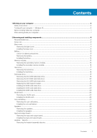
instructions...6 Turning off your computer - Windows 10...6 Before working inside your computer...7 After working inside your computer...7 2 Removing and installing components 8 Recommended tools...8 Screw List...8 Base cover...9 Removing the base cover...9 Installing the base cover...11 Battery - Dell Vostro 5490 | Service Manual - Page 4
...66 Secure boot...67 Performance...67 Power management...68 Wireless...69 POST behavior...69 Virtualization support...69 Maintenance...70 System logs...70 Updating the BIOS in Windows ...70 Updating BIOS on systems with BitLocker enabled 71 Updating your system BIOS using a USB flash drive 71 - Dell Vostro 5490 | Service Manual - Page 5
4 Troubleshooting...74 Enhanced Pre-Boot System Assessment (ePSA) diagnostics 74 Running the ePSA diagnostics...74 Diagnostics...74 M-BIST...75 L-BIST...75 System diagnostic lights...75 WiFi power cycle...76 5 Getting help...77 Contacting Dell...77 Contents 5 - Dell Vostro 5490 | Service Manual - Page 6
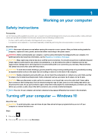
all power sources troubleshooting and simple repairs as authorized in your product documentation, or as directed by the online or telephone service and support team. Damage due to servicing that is not authorized by Dell is not covered by your warranty. Read and follow the safety instructions - Dell Vostro 5490 | Service Manual - Page 7
turn off when you shut down your operating system, press and hold the power button for about 6 seconds to turn them off. Before working inside your begin working inside the computer. Steps 1. Ensure that you follow the Safety Instruction. 2. Ensure that your work surface is flat and clean to prevent - Dell Vostro 5490 | Service Manual - Page 8
• Plastic scribe NOTE: The #0 screw driver is for screws 0-1 and the #1 screw driver is for screws 2-4 Screw List The following Battery M2x3 3 WLAN M2x3 1 System fan M2x3 2 DC-In M2x3 1 SSD M2x3 1 Input output board M2x3 2 USB Type-C bracket M2x3 2 HDD assembly M2x3 4 Power - Dell Vostro 5490 | Service Manual - Page 9
Hinge plate Screw type M2x2 Big Head M2x2 (Big Head) M2.5x5 Quantity 3 4 6 Image Heatsink - UMA Heatsink - Discrete System board Fingerprint board Power button board Display Hinges M2x3 4 M2x3 7 M2x2 (Big head) 5 M2x2 (Big Head) 2 M2x2 (Big Head) 2 M2.5x2.5 (Big Head) 6 Base cover - Dell Vostro 5490 | Service Manual - Page 10
10 Removing and installing components - Dell Vostro 5490 | Service Manual - Page 11
Steps 1. Loosen the four (M2x8) captive screws and remove the five (M2x5) screws that secure the base cover to the computer. 2. Pry the base cover starting from the right hinge and work your way around. 3. Lift the base cover away from the computer. Installing the base cover Prerequisites If you are - Dell Vostro 5490 | Service Manual - Page 12
12 Removing and installing components - Dell Vostro 5490 | Service Manual - Page 13
to the computer. Next steps 1. Follow the procedure in After working inside your computer. Battery Lithium-ion battery precautions CAUTION: • Exercise caution when handling Lithium-ion batteries. • Discharge the battery as much as possible before removing it from the system. This can be done by - Dell Vostro 5490 | Service Manual - Page 14
and further instructions. • If the battery gets stuck inside your computer as a result of swelling, do not try to release it as puncturing, bending, or crushing a lithium-ion battery can be dangerous. In such an instance, contact Dell technical support for assistance. See www.dell.com/contactdell - Dell Vostro 5490 | Service Manual - Page 15
with the screw holes on the palmrest. 2. Replace the three (M2x3) screws to secure the battery to the palmrest. 3. Connect the battery cable to the connector on the system board. Next steps 1. Install the base cover. 2. Follow the procedure in After working inside your computer. Memory modules - Dell Vostro 5490 | Service Manual - Page 16
1. Follow the procedure in Before working inside your computer. 2. Remove the base cover. 3. Remove the battery. About this task The figure indicates the location of the memory module and provides a visual representation of the removal procedure. Steps 1. Peel the adhesive tape, - Dell Vostro 5490 | Service Manual - Page 17
hear the click, remove the memory module and reinstall it. 4. Affix the adhesive tape above the memory module. Next steps 1. Install the battery. 2. Install the base cover. 3. Follow the procedure in After working inside your computer. Hard drive Removing the hard drive Prerequisites 1. Follow the - Dell Vostro 5490 | Service Manual - Page 18
Steps 1. Release the latch and disconnect the hard-drive cable from the connector on the system board. 2. Remove the four (M2x3) screws that secure the hard-drive module to the palmrest assembly. 3. Slide the hard-drive module out from the computer. Installing the hard drive Prerequisites If you are - Dell Vostro 5490 | Service Manual - Page 19
the hard-drive cable to the connector on the system board and close the latch to secure the cable. Next steps 1. Install the battery. 2. Install the base cover. 3. Follow the procedure in After working inside your computer. Solid state drive Removing the M.2 2230 solid-state drive Prerequisites - Dell Vostro 5490 | Service Manual - Page 20
the M.2 2242 solid-state drive Prerequisites 1. Follow the procedure in Before working inside your computer. 2. Remove the base cover. 3. Remove the battery. About this task The figure indicates the location of the M.2 2242 solid-state drive and provides a visual representation of the removal - Dell Vostro 5490 | Service Manual - Page 21
assembly. 2. Slide the solid-state module out from the M.2 slot. Replacing the SSD support bracket Prerequisites 1. Follow the procedure in Before working inside your computer. 2. Remove the base cover. 3. Remove the battery. 4. Remove the M.2 2230 SSD or M.2 2242 SSD or M.2 2280 SSD. About this - Dell Vostro 5490 | Service Manual - Page 22
bracket slot. 2. Depending on the type of solid-state drive (M.2 2230/ M.2 2242/ M.2 2280), align and insert the SSD support bracket into the support bracket slot. 3. Install the solid-state drive. Installing M.2 2230 solid-state drive Prerequisites If you are replacing a component, remove the - Dell Vostro 5490 | Service Manual - Page 23
2. Replace the single (M2x3) screw to secure the solid-state drive module to the palmrest and keyboard assembly. Next steps 1. Install the battery. 2. Install the base cover. 3. Follow the procedure in After working inside your computer. Installing M.2 2242 solid-state drive Prerequisites If you are - Dell Vostro 5490 | Service Manual - Page 24
M.2 slot. 2. Replace the single (M2x3) screw to secure the solid-state drive module to the palmrest assembly. Next steps 1. Install the battery. 2. Install the base cover. 3. Follow the procedure in After working inside your computer. Installing M.2 2280 solid-state drive Prerequisites If you are - Dell Vostro 5490 | Service Manual - Page 25
the M.2 slot. 2. Replace the single (M2x3) screw to secure the solid-state drive module to the palmrest assembly. Next steps 1. Install the battery. 2. Install the base cover. 3. Follow the procedure in After working inside your computer. WLAN card Removing the WLAN card Prerequisites 1. Follow the - Dell Vostro 5490 | Service Manual - Page 26
Steps 1. Remove the single (M2x3) screw that secures the WLAN bracket to the computer. 2. Remove the WLAN bracket. 3. Disconnect the WLAN antenna cables from the WLAN module. 4. Slide and remove the WLAN card from the WLAN card slot. Installing the WLAN card Prerequisites If you are replacing a - Dell Vostro 5490 | Service Manual - Page 27
the WLAN card to the system board. Next steps 1. Install the battery. 2. Install the base cover. 3. Follow the procedure in After working inside your computer. Coin-cell battery Removing the coin-cell battery Prerequisites 1. Follow the procedure in Before working inside your computer. 2. Remove - Dell Vostro 5490 | Service Manual - Page 28
the removal procedure. Steps 1. Disconnect the coin-cell battery cable from the system board. 2. Remove the coin-cell battery cable from the routing guide. 3. Peel the coin-cell battery off the palmrest assembly. Installing the coin-cell battery Prerequisites If you are replacing a component, remove - Dell Vostro 5490 | Service Manual - Page 29
to the slot on the palmrest assembly. 2. Route the coin-cell battery cable through the routing guide. 3. Connect the coin-cell battery cable to the system board. Next steps 1. Install the battery. 2. Install the base cover. 3. Follow the procedure in After working inside your computer. Speakers - Dell Vostro 5490 | Service Manual - Page 30
Steps 1. Locate the speakers on your computer. 2. Disconnect the speaker cable from the connector on the system board. 3. Peel the adhesive tape that secures the speaker cable. 4. Unroute the speaker cables from the retention clips on the computer. 5. Lift the speakers out of the computer. - Dell Vostro 5490 | Service Manual - Page 31
. 4. Route the speaker cables through the retention clips on your computer. 5. Adhere the adhesive tape to secure the speaker cable. Next steps 1. Install the battery. 2. Install the base cover. 3. Follow the procedure in After working inside your computer. Removing and installing components 31 - Dell Vostro 5490 | Service Manual - Page 32
the input and output board Prerequisites 1. Follow the procedure in Before working inside your computer. 2. Remove the base cover. 3. Remove the battery. About this task The figure indicates the location of the input and output board and provides a visual representation of the removal procedure - Dell Vostro 5490 | Service Manual - Page 33
to the connector on the system board. 4. Route the input and output board cables through the retention clips on your computer. Next steps 1. Install the battery. Removing and installing components 33 - Dell Vostro 5490 | Service Manual - Page 34
the heatsink assembly-discrete Prerequisites 1. Follow the procedure in Before working inside your computer. 2. Remove the base cover. 3. Remove the battery. About this task The figure indicates the location of the heatsink assembly and provides a visual representation of the removal procedure - Dell Vostro 5490 | Service Manual - Page 35
2. Remove the seven (M2x3) screws that secure the heatsink assembly to the system board. NOTE: Remove the screws in the order of the callout numbers [1, 2, 3, 4, 5, 6, 7] as indicated on the heatsink. 3. Lift the heatsink assembly out of the computer. Installing the heatsink assembly-discrete - Dell Vostro 5490 | Service Manual - Page 36
fan Removing the system fan Prerequisites 1. Follow the procedure in Before working inside your computer. 2. Remove the base cover. 3. Remove the battery. About this task The figure indicates the location of the system fan and provides a visual representation of the removal procedure. 36 Removing - Dell Vostro 5490 | Service Manual - Page 37
Steps 1. Lift the latch and disconnect the input and output board cable from the connector on the system board. 2. Unroute the input and output board cable from the retention clips. 3. Disconnect the system fan cable from the connector on the system board. 4. Remove the two (M2x3) screws that secure - Dell Vostro 5490 | Service Manual - Page 38
the retention clip and connect the input and output board cable to the connector on the system board. Next steps 1. Install the battery. 2. Install the base cover. 3. Follow the procedure in After working inside your computer. Touchpad Removing the touchpad Prerequisites 1. Follow the procedure in - Dell Vostro 5490 | Service Manual - Page 39
Steps 1. Locate the touchpad on your computer. 2. Peel the adhesive that secures the speaker cable to the touchpad bracket. 3. Remove the three (M2x2) screws that secure the touchpad bracket to the touchpad. 4. Remove the touchpad bracket away from the computer. 5. Lift the latch and disconnect the - Dell Vostro 5490 | Service Manual - Page 40
. 7. Replace the three (M2x2) screws to secure the touchpad bracket to the touchpad. 8. Adhere the adhesive to route the speaker cable. Next steps 1. Install the battery. 2. Install the base cover. 3. Follow the procedure in After working inside your computer. 40 Removing and installing components - Dell Vostro 5490 | Service Manual - Page 41
inside your computer. 2. Remove the base cover. 3. Remove the battery. About this task The figure indicates the location of the power-adapter and provides a visual representation of the removal procedure. Steps 1. Locate the power-adapter port on your computer. 2. Remove the three (M2.5x5) screws - Dell Vostro 5490 | Service Manual - Page 42
-adapter port to the palmrest assembly. 4. Connect the power-adapter cable to the connector on the system board. 5. Close the left hinge. 6. Replace the three (M2.5x5) screws that secure the left hinge to the system board. Next steps 1. Install the battery. 2. Install the base cover. 3. Follow the - Dell Vostro 5490 | Service Manual - Page 43
in Before working inside your computer. 2. Remove the base cover. 3. Remove the battery. 4. Remove the M.2 2230 SSD or M.2 2242 SSD or M.2 2280 SSD -discrete. 8. Remove the input and output board. 9. Remove the power-adapter port. About this task The figure indicates the location of the system board - Dell Vostro 5490 | Service Manual - Page 44
angle. 4. Disconnect the power-adapter port cable from the connector in the system board. 5. Lift the latch and disconnect the power button cable from the that secures the WLAN antenna cables. 9. Disconnect the coin-cell battery cable and the speaker cable from the connectors on the system board - Dell Vostro 5490 | Service Manual - Page 45
Removing and installing components 45 - Dell Vostro 5490 | Service Manual - Page 46
screws to secure the system board to the palmrest assembly. 4. Connect the power-adapter port cable to the connector on the system board. 5. Close the left hinge antenna cables to the system board. 10. Connect the coin-cell battery cable and the speaker cable to the connectors on the system board. - Dell Vostro 5490 | Service Manual - Page 47
Install the M.2 2230 SSD or M.2 2242 SSD or M.2 2280 SSD. 7. Install the battery. 8. Install the base cover. 9. Follow the procedure in After working inside your computer. Power button Removing the power button Prerequisites 1. Follow the procedure in Before working inside your computer. 2. Remove - Dell Vostro 5490 | Service Manual - Page 48
6. Remove the two (M2x2) screws and the two (M2x3) screws that secure the power button to the palmrest assembly. 7. Lift the power button out of the computer. Installing the power button Prerequisites If you are replacing a component, remove the existing component before performing the installation - Dell Vostro 5490 | Service Manual - Page 49
M2x3) screws to secure the power button to the palmrest assembly. 4. Adhere the adhesive tape above the power button. 5. Connect the power button cable to the connector and output board. 2. Install the system fan. 3. Install the battery. 4. Install the base cover. 5. Follow the procedure in After - Dell Vostro 5490 | Service Manual - Page 50
in Before working inside your computer. 2. Remove the base cover. 3. Remove the battery. 4. Remove the system fan. 5. Remove the input and output board. About this task The figure indicates the location of the power button with fingerprint reader and provides a visual representation of the removal - Dell Vostro 5490 | Service Manual - Page 51
to the palmrest assembly. 7. Remove the two (M2x3) screws that secure the power button to the palmrest assembly 8. Lift the power button with fingerprint reader off the palmrest assembly. Installing the power button with fingerprint reader Prerequisites If you are replacing a component, remove the - Dell Vostro 5490 | Service Manual - Page 52
6. Connect the power button cable to the connector on the system board. 7. Close the right display hinge and replace the two (M2.5x5) screws to secure the right display hinge to the palmrest assembly. Next steps 1. Install the Input and output board. 2. Install the system fan. 3. Install the battery - Dell Vostro 5490 | Service Manual - Page 53
Removing and installing components 53 - Dell Vostro 5490 | Service Manual - Page 54
54 Removing and installing components - Dell Vostro 5490 | Service Manual - Page 55
Removing and installing components 55 - Dell Vostro 5490 | Service Manual - Page 56
Steps 1. Peel the tape that secures the display cable connector to the system board. 2. Open the latch and disconnect the display cable from the system board. 3. Remove the six (M2.5x2.5) screws that secure the left and right display hinges to the chassis of your computer. 4. Open the display hinges - Dell Vostro 5490 | Service Manual - Page 57
Removing and installing components 57 - Dell Vostro 5490 | Service Manual - Page 58
58 Removing and installing components - Dell Vostro 5490 | Service Manual - Page 59
cable to the system board and adhere the tape to secure the display cable. Next steps 1. Install the system fan. 2. Install the battery. 3. Install the base cover. 4. Follow the procedure in After working inside your computer. Palmrest assembly Replacing the palmrest assembly Prerequisites 1. Follow - Dell Vostro 5490 | Service Manual - Page 60
touchpad. 5. Install the power-adapter port. 6. Install the system fan. 7. Install the input and output board. 8. Install the WLAN card. 9. Install the memory. 10. Install the M.2 2230 SSD or M.2 2242 SSD or M.2 2280 SSD. 11. Install the speakers 12. Install the coin-cell battery. 13. Install the - Dell Vostro 5490 | Service Manual - Page 61
BIOS Setup program screen information for future reference. Use the BIOS Setup program for the following purposes: • Get information about the hardware installed in your computer, such as the amount of RAM Updating the BIOS in Windows • System and setup password Boot menu Press when the Dell - Dell Vostro 5490 | Service Manual - Page 62
Power-on Self Test (POST), when the Dell Vostro 5490 Battery Processor Memory Devices . Description Displays the following information: • BIOS Version, Service Tag, Asset Tag, Ownership Tag, Manufacture Date, Ownership Date, Express Service Code, and the Signed Firmware Update. Displays the battery - Dell Vostro 5490 | Service Manual - Page 63
. This option controls: • Disabled • Enabled • Enabled with PXE • Enable UEFI Network Stack: (enabled by default) Storage Interface Displays the following: • Port Enablement: This page allows you to select the onboard drives you would like to enable. • SATA-0 (enabled by default) • M.2 PCIe SSD - Dell Vostro 5490 | Service Manual - Page 64
USB ports are functional in an OS environment: • Enable USB Boot Support • Enable External USB Ports 15 min • Never Keyboard Backlight Timeout on Battery This feature defines the timeout value for the keyboard backlight when the system is running only on battery power. • 5 sec • 10 sec-enabled - Dell Vostro 5490 | Service Manual - Page 65
. This option controls whether this system allows BIOS updates via UEFI capsule update packages. This option is selected by default. Disabling this option will block BIOS updates from services such as Microsoft Windows Update and Linux Vendor Firmware Service (LVFS) This option lets you bypass the - Dell Vostro 5490 | Service Manual - Page 66
Enable, Disable or Permanently Disable the BIOS module interface of the optional Absolute Persistence Module service from Absolute Software. • Enabled - you to set the System password. This field disables the master password support. Hard disk passwords need to be cleared before the setting can - Dell Vostro 5490 | Service Manual - Page 67
Table 9. Performance Option Multi Core Support Intel SpeedStep Enable C-States Control behavior of Secure Boot to allow evaluation or enforcement of UEFI driver signatures. • Deployed Mode (default) • Audit Mode Allows power states. • C states This option is set by default. System setup 67 - Dell Vostro 5490 | Service Manual - Page 68
functionality allows the system to run on battery during peak power usage hours. The options are: • Adaptive-enabled by default • Standard-Fully charges your battery at a standard rate. • ExpressCharge-The battery charges over a shorter time using Dell's fast charging technology. • Primarily AC use - Dell Vostro 5490 | Service Manual - Page 69
to enable or disable the system setup (BIOS) warning messages when you use certain power adapters. Default setting: Enable Adapter Warnings • Continue on warnings and errors Virtualization support Table 12. Virtualization support Options Intel Virtualization Technology Descriptions This field - Dell Vostro 5490 | Service Manual - Page 70
be suspended prior to updating the system BIOS, and then re-enabled after the BIOS update is completed. Steps 1. Restart the computer. 2. Go to Dell.com/support. • Enter the Service Tag or Express Service Code and click Submit. • Click Detect Product and follow the instructions on screen. 3. If you - Dell Vostro 5490 | Service Manual - Page 71
updated BIOS settings on your computer. Follow the instructions on the screen. Updating BIOS on systems with BitLocker enabled CAUTION: If BitLocker is not suspended before updating the BIOS details: https:// www.dell.com/support/article/sln143196/ Steps 1. Download the BIOS update .EXE file to - Dell Vostro 5490 | Service Manual - Page 72
Password only when the status is in Not Set. About this task To enter the system setup, press F2 immediately after a power-on or re-boot. Steps 1. In the System BIOS or System Setup screen, select Security and press Enter. The Security screen is displayed. 2. Select System/Admin Password and create - Dell Vostro 5490 | Service Manual - Page 73
Setup password, if the Password Status is Locked. About this task To enter the System Setup, press F2 immediately after a power-on or reboot. Steps 1. In the System BIOS or System Setup screen, select System Security and press Enter. The System Security screen is displayed. 2. In the System Security - Dell Vostro 5490 | Service Manual - Page 74
is supplying power to the LCD display by performing an LCD Power Rail test, which allows for isolation of "No Video" symptom to Mainboard, LCD or Cable. Pressing M key and Power button Integrated into the single LED error code diagnostic. Automatically initiated during POST. 74 Troubleshooting - Dell Vostro 5490 | Service Manual - Page 75
followed by a pause, and then blinks white three times followed by a pause. This 2,3 pattern continues until the computer is turned off indicating no memory or RAM is detected. The following table shows different power and battery-status light patterns and associated problems. Troubleshooting 75 - Dell Vostro 5490 | Service Manual - Page 76
to access the internet due to WiFi connectivity issues a WiFi power cycle procedure may be performed. The following procedure provides the instructions on how to conduct a WiFi power cycle: NOTE: Some ISPs (Internet Service Providers) provide a modem/router combo device. Steps 1. Turn off your - Dell Vostro 5490 | Service Manual - Page 77
. Availability varies by country and product, and some services may not be available in your area. To contact Dell for sales, technical support, or customer service issues: Steps 1. Go to Dell.com/support. 2. Select your support category. 3. Verify your country or region in the Choose a Country
-
 1
1 -
 2
2 -
 3
3 -
 4
4 -
 5
5 -
 6
6 -
 7
7 -
8
-
9
-
10
-
11
-
12
-
13
-
14
-
15
-
16
-
17
-
18
-
19
-
20
-
21
-
22
-
23
-
24
-
25
-
26
-
27
-
28
-
29
-
30
-
31
-
32
-
33
-
34
-
35
-
36
-
37
-
38
-
39
-
40
-
41
-
42
-
43
-
44
-
45
-
46
-
47
-
48
-
49
-
50
-
51
-
52
-
53
-
54
-
55
-
56
-
57
-
58
-
59
-
60
-
61
-
62
-
63
-
64
-
65
-
66
-
67
-
68
-
69
-
70
-
71
-
72
-
73
-
74
-
75
-
76
-
77
 |
 |

Dell Vostro 5490
Service Manual
Regulatory Model: P116G
Regulatory Type: P116G001