Dell W-Series 228 W-AP228 Access Point Installation Guide - Page 3
Table 2, USB Console Port, Ethernet Ports, Reset Button, Table 3
 |
View all Dell W-Series 228 manuals
Add to My Manuals
Save this manual to your list of manuals |
Page 3 highlights
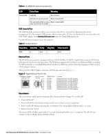
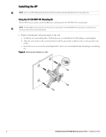
Table 2 W-AP228 LED Status during Operation LED System LED Color/State Meaning Solid Red General fault One blink off every 3 seconds Radio 0 fault (5 GHz) Two quick blink off 0.5 seconds Radio 1 fault (2.4GHz) apart cycled every 3 seconds USB Console Port The USB Micro-B console port allows you to connect the AP to a terminal or a laptop for direct local management. Use the included USB console cable to connect the AP. You can download the necessary driver for USB-UART adapter from download.dell-pcw.com under the Tools & Resources tab. Use the following setting to access the terminal: Table 3 Console Settings Baud Rate Data Bits Parity Stop Bits Flow Control 9600 8 None 1 None Ethernet Ports The W-AP228 access point is equipped with two 10/100/1000Base-T (RJ-45) Gigabit Ethernet ports (WAN and LAN port) for wired network connectivity. The WAN port supports 802.3at Power over Ethernet (PoE), accepting 48 VDC (nominal) as a standard defined Powered Device (PD) from a Power Sourcing Equipment (PSE) such as a PoE midspan injector. These ports have RJ-45 female connectors with the pin-outs shown in Figure 3. Figure 3 Gigabit Ethernet Port Pin-Out 1000Base-T Gigabit Ethernet Port RJ-45 Female Pin-Out 1 2 3 4 5 6 7 8 Signal Name BI_DA+ BI_DABI_DB+ BI_DC+ BI_DCBI_DBBI_DD+ BI_DD- Function Bi-directional pair +A, POE Negative Bi-directional pair -A, POE Negative Bi-directional pair +B, POE Positive Bi-directional pair +C, POE Positive Bi-directional pair -C, POE Positive Bi-directional pair -B, POE Positive Bi-directional pair +D, POE Negative Bi-directional pair -D, POE Negative Reset Button The reset button can be used to return the AP to factory default settings. To reset the AP: 1. Power off the AP. 2. Press and hold the reset button using a small, narrow object, such as a paperclip. 3. Power-on the AP without releasing the reset button. The system LED will flash within 5 seconds. 4. Release the reset button. The system LED will flash again within 15 seconds indicating that the reset is completed. The AP will now continue to boot with the factory default settings. Dell Networking W-AP228 Wireless Access Point | Installation Guide 3
-
 1
1 -
 2
2 -
 3
3 -
 4
4 -
 5
5 -
 6
6 -
 7
7 -
 8
8 -
 9
9 -
10
-
11
-
12
-
13
-
14
-
15
-
16
 |
 |
