Dell W-Series 228 W-AP228 Access Point Installation Guide - Page 8
Grounding the AP, Connecting the Ethernet Cable
 |
View all Dell W-Series 228 manuals
Add to My Manuals
Save this manual to your list of manuals |
Page 8 highlights
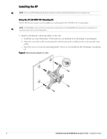
Figure 8 Completed Installation Grounding the AP After the W-AP228 access point is mounted, it must be grounded before powering up. The grounding wire should be #8 AWG. 1. Peel the cover of one end of the grounding wire and place the bare grounding wire into the included copper lug, and press firmly with the crimping pliers. 2. Fasten the copper lug to the grounding hole on the AP with the M4 x6 screw included in the AP package, as shown in Figure 2. Connecting the Ethernet Cable To connect the Ethernet cable to the AP, perform the following steps using the cable glands that ships with your AP. WARNING: Failure to use the included Ethernet cable glands can lead to connectivity and POE issues. NOTE: The Ethernet cable is not included and must be purchased separately. Purchase a suitable UV-resistant, outdoor rated, CAT 5E or better RJ45 cable for use with the AP. Figure 9 Installing a Cable Gland Seal Sealing Nut Clamping Ring CAT 5E or Better Cable 1. Slide the sealing nut over the cable (without the RJ45 connector attached to the end). 2. Slide the clamping ring over the cable. 3. Using a crimping tool, attach the shielded RJ45 connector to the end of the cable. 8 Dell Networking W-AP228 Wireless Access Point | Installation Guide
-
 1
1 -
2
-
 3
3 -
 4
4 -
 5
5 -
 6
6 -
 7
7 -
 8
8 -
 9
9 -
 10
10 -
 11
11 -
 12
12 -
 13
13 -
14
-
15
-
16
 |
 |
