Dell XPS M1710 MXG061 XPS M1710 Service Manual
Dell XPS M1710 MXG061 Manual
 |
View all Dell XPS M1710 MXG061 manuals
Add to My Manuals
Save this manual to your list of manuals |
Dell XPS M1710 MXG061 manual content summary:
- Dell XPS M1710 MXG061 | XPS M1710 Service Manual - Page 1
Dell™ XPS™ M1710 Service Manual Before You Begin Optical Drive Hard Drive Memory Module(s) indicates either potential damage to hardware or loss of data and tells you how to avoid the problem. CAUTION: A CAUTION indicates a potential for property damage, personal injury, or death. Abbreviations - Dell XPS M1710 MXG061 | XPS M1710 Service Manual - Page 2
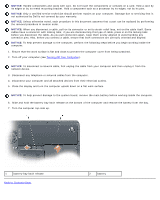
Back to Contents Page Before You Begin Dell™ XPS™ M1710 Service Manual Recommended Tools Turning Off Your Computer Before Working Inside Your Computer This section provides : Before you begin any of the procedures in this section, follow the safety instructions in the Product Information Guide. - Dell XPS M1710 MXG061 | XPS M1710 Service Manual - Page 3
a component such as a processor by its edges, not by its pins. NOTICE: Only a certified service technician should perform repairs on your computer. Damage due to servicing that is not authorized by Dell is not covered by your warranty. NOTICE: Unless otherwise noted, each procedure in this document - Dell XPS M1710 MXG061 | XPS M1710 Service Manual - Page 4
Back to Contents Page Subwoofer Dell™ XPS™ M1710 Service Manual CAUTION: Before you begin the following procedure, follow the safety instructions in the Product Information Guide. NOTICE: To avoid electrostatic discharge, ground yourself by using a wrist grounding strap or by periodically touching - Dell XPS M1710 MXG061 | XPS M1710 Service Manual - Page 5
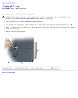
Back to Contents Page Optical Drive Dell™ XPS™ M1710 Service Manual Your computer ships with a fixed optical drive installed. NOTICE: To help prevent damage to drives, store them in a safe, dry place when they are not - Dell XPS M1710 MXG061 | XPS M1710 Service Manual - Page 6
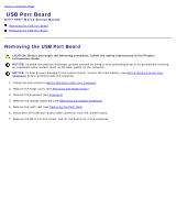
to Contents Page USB Port Board Dell™ XPS™ M1710 Service Manual Removing the USB Port Board Replacing the USB Port Board Removing the USB Port Board CAUTION: Before you begin the following procedure, follow the safety instructions in the Product Information Guide. NOTICE: To avoid electrostatic - Dell XPS M1710 MXG061 | XPS M1710 Service Manual - Page 7
1 USB port board 4 USB-port-board cable 7 pin 2 M2.5 x 5-mm screw 5 system board connector 3 notch 6 tab Replacing the USB Port Board 1. Insert the notch on the USB port board under the small tab on the computer base and the other side of the board over the pin. 2. Replace the M2.5 x 5-mm screw. - Dell XPS M1710 MXG061 | XPS M1710 Service Manual - Page 8
Dell™ XPS™ M1710 Service Manual Removing the Hard Drive Replacing the Hard Drive Returning a Hard Drive to Dell Dell does not guarantee compatibility or provide support for hard drives from sources other than Dell. 1. Follow the instructions Guide. 3. Slide the hard drive out of the computer. - Dell XPS M1710 MXG061 | XPS M1710 Service Manual - Page 9
have installed a replacement hard drive, reinstall the Microsoft® Windows® operating system. For instructions, see "Restoring Your Operating System" in the Owner's Manual. Instructions for alternative solutions are available at support.dell.com/pcrt. 4. Reinstall drivers on the new hard drive. For - Dell XPS M1710 MXG061 | XPS M1710 Service Manual - Page 10
Dell™ XPS™ M1710 Service Manual Removing the Processor Thermal-Cooling Assembly Replacing the Processor Thermal-Cooling Assembly Removing the Processor Thermal-Cooling Assembly CAUTION: Before you begin the following procedure, follow the safety instructions in the Product Information Guide - Dell XPS M1710 MXG061 | XPS M1710 Service Manual - Page 11
Replacing the Processor Thermal-Cooling Assembly 1. Place a new thermal pad over the old thermal pad on the thermal-cooling assembly: a. Remove the backing from the new thermal pad, taking care not to tear the pad. NOTE: You can place the new thermal pad directly on any existing thermal pad already - Dell XPS M1710 MXG061 | XPS M1710 Service Manual - Page 12
Contents Page Memory Module(s) Dell™ XPS™ M1710 Service Manual Removing the Memory Module(s) Replacing the Memory Module(s) Removing the Memory Module(s) CAUTION: Before you begin the following procedure, follow the safety instructions in the Product Information Guide. NOTICE: To prevent static - Dell XPS M1710 MXG061 | XPS M1710 Service Manual - Page 13
1 memory module 2 securing clips (2) Replacing the Memory Module(s) NOTE: To get maximum performance/dual-channel memory bandwidth capability, both memory module connectors must contain memory modules and the modules must be of the same size and configuration. NOTE: If a memory module is not - Dell XPS M1710 MXG061 | XPS M1710 Service Manual - Page 14
NOTICE: If the memory module cover is difficult to close, remove the module and reinstall it. Forcing the cover to close may damage your computer. 3. Insert the battery into the battery bay, and connect the AC adapter to your computer and an electrical outlet. 4. Turn on the computer. As the - Dell XPS M1710 MXG061 | XPS M1710 Service Manual - Page 15
Back to Contents Page Processor Module Dell™ XPS™ M1710 Service Manual Removing the Processor Module Replacing the Processor Module Removing the Processor Module CAUTION: Before you begin the following procedure, follow the safety instructions in the Product Information Guide. NOTICE: To avoid - Dell XPS M1710 MXG061 | XPS M1710 Service Manual - Page 16
1 ZIF-socket cam screw 2 pin-1 corner of microprocessor 3 ZIF-socket NOTE: The ZIF-socket cam screw secures the processor to the system board. 8. Lift the processor module from the ZIF socket. Replacing the Processor Module NOTICE: Ensure that the cam lock is in the fully open position before - Dell XPS M1710 MXG061 | XPS M1710 Service Manual - Page 17
3. Replace the processor thermal-cooling assembly (see Replacing the Processor Thermal-Cooling Assembly). 4. Replace in reverse order the remaining components that you removed in Removing the Processor Module, beginning with step 5. Back to Contents Page - Dell XPS M1710 MXG061 | XPS M1710 Service Manual - Page 18
Back to Contents Page Modem Dell™ XPS™ M1710 Service Manual Removing the Modem Replacing the Modem Removing the Modem CAUTION: Before you begin the following procedure, follow the safety instructions in the Product Information Guide. NOTICE: To avoid electrostatic discharge, ground yourself by - Dell XPS M1710 MXG061 | XPS M1710 Service Manual - Page 19
1 system board connector 4 modem 2 M2 x 3-mm screw 5 modem cable 3 pull-tab NOTICE: Do not disconnect the modem cable from the system board. 5. Disconnect the modem cable from the modem. Replacing the Modem 1. Connect the modem cable to the modem. NOTICE: Ensure that the modem cable is routed - Dell XPS M1710 MXG061 | XPS M1710 Service Manual - Page 20
Dell™ XPS™ M1710 Service Manual Removing the Video Card/Thermal-Cooling Assembly Replacing the Video Card/Thermal-Cooling Assembly Removing the Video Card/Thermal-Cooling Assembly CAUTION: Before you begin the following procedure, follow the safety instructions in the Product Information Guide - Dell XPS M1710 MXG061 | XPS M1710 Service Manual - Page 21
1 captive screws (4) 2 video card/thermal-cooling assembly 3 system board connector Replacing the Video Card/Thermal-Cooling Assembly NOTE: Ensure that the video card/thermal-cooling assembly mylar flap rests on top of the processor thermal-cooling assembly when the video card/thermal-cooling - Dell XPS M1710 MXG061 | XPS M1710 Service Manual - Page 22
Back to Contents Page Mini-Card Dell™ XPS™ M1710 Service Manual CAUTION: Before you begin the following procedure, follow the safety instructions in the Product Information Guide. CAUTION: Only products approved for use in your portable computer may be installed. NOTICE: To avoid electrostatic - Dell XPS M1710 MXG061 | XPS M1710 Service Manual - Page 23
1 antenna connectors (2) 2 Mini-Card 3 Mini-Card connector b. Release the Mini-Card by pushing the metal securing clips toward the back of the computer until the card pops up slightly. c. Lift the Mini-Card out of its connector. 1 Mini-Card 2 securing clips (2) NOTICE: The connectors are - Dell XPS M1710 MXG061 | XPS M1710 Service Manual - Page 24
1 triangles (2) 4 securing clips (2) 2 Mini-Card connector 3 antenna connectors (2) NOTICE: To avoid damaging the Mini-Card, never place cables under the card. NOTE: If you are installing a Mini-Card for the first time, you will find a clear plastic protective sleeve on each antenna cable - Dell XPS M1710 MXG061 | XPS M1710 Service Manual - Page 25
- Dell XPS M1710 MXG061 | XPS M1710 Service Manual - Page 26
Back to Contents Page System Fan(s) Dell™ XPS™ M1710 Service Manual CAUTION: Before you begin the following procedure, follow the safety instructions in the Product Information Guide. NOTICE: To avoid electrostatic discharge, ground yourself by using a wrist grounding strap or by periodically - Dell XPS M1710 MXG061 | XPS M1710 Service Manual - Page 27
1 M2.5 x 5-mm screws (2) 4 connectors on system board (2) 2 fan for video card/thermal- cooling assembly, 3 fan cables if installed (2) Back to Contents Page - Dell XPS M1710 MXG061 | XPS M1710 Service Manual - Page 28
Back to Contents Page Internal Card With Bluetooth® Wireless Technology Dell™ XPS™ M1710 Service Manual CAUTION: Before you begin the following procedure, follow the safety instructions in the Product Information Guide. NOTICE: To avoid electrostatic discharge, ground yourself by using a wrist - Dell XPS M1710 MXG061 | XPS M1710 Service Manual - Page 29
Back to Contents Page ExpressCard Cage Dell™ XPS™ M1710 Service Manual CAUTION: Before you begin the following procedure, follow the safety instructions in the Product Information Guide. NOTICE: To avoid electrostatic discharge, ground yourself by using a wrist grounding strap or by periodically - Dell XPS M1710 MXG061 | XPS M1710 Service Manual - Page 30
Back to Contents Page - Dell XPS M1710 MXG061 | XPS M1710 Service Manual - Page 31
to Contents Page Hinge Cover Dell™ XPS™ M1710 Service Manual Removing the Hinge Cover Replacing the Hinge Cover Removing the Hinge Cover CAUTION: Before you begin the following procedure, follow the safety instructions in the Product Information Guide. NOTICE: To avoid electrostatic discharge - Dell XPS M1710 MXG061 | XPS M1710 Service Manual - Page 32
Back to Contents Page - Dell XPS M1710 MXG061 | XPS M1710 Service Manual - Page 33
Back to Contents Page Smart Card Reader Dell™ XPS™ M1710 Service Manual CAUTION: Before you begin the following procedure, follow the safety instructions in the Product Information Guide. NOTICE: To avoid electrostatic discharge, ground yourself by using a wrist grounding strap or by periodically - Dell XPS M1710 MXG061 | XPS M1710 Service Manual - Page 34
Back to Contents Page - Dell XPS M1710 MXG061 | XPS M1710 Service Manual - Page 35
Back to Contents Page Keyboard Dell™ XPS™ M1710 Service Manual CAUTION: Before you begin the following procedure, follow the safety instructions in the Product Information Guide. NOTICE: To avoid electrostatic discharge, ground yourself by using a wrist grounding strap or by periodically touching an - Dell XPS M1710 MXG061 | XPS M1710 Service Manual - Page 36
- Dell XPS M1710 MXG061 | XPS M1710 Service Manual - Page 37
Back to Contents Page System Board Dell™ XPS™ M1710 Service Manual Removing the System Board Replacing the System Board Removing the System Board CAUTION: Before you begin the following procedure, follow the safety instructions in the Product Information Guide. NOTICE: To avoid electrostatic - Dell XPS M1710 MXG061 | XPS M1710 Service Manual - Page 38
1 ExpressCard connector 2 ExpressCard connector on system board 1 USB-port-board connector 2 subwoofer connector 3 speaker connectors (2) 4 cable connector for internal card with Bluetooth wireless technology 12. Disconnect the smart-card reader connector from the system board. 13. Disconnect - Dell XPS M1710 MXG061 | XPS M1710 Service Manual - Page 39
18. Remove the video card/thermal-cooling assembly, if present (see Removing the Video Card/Thermal- Cooling Assembly). NOTE: Remove the video card/thermal-cooling assembly as a single unit. Do not separate the thermal-cooling unit (heat sink) from the video card. 19. Remove the processor thermal- - Dell XPS M1710 MXG061 | XPS M1710 Service Manual - Page 40
1 system board M2.5 x 5-mm screws (4) 23. Remove the system board, slowly easing the connectors out of their access holes on the back and side of the computer base: a. With the back of the computer facing you, grasp the upper-right corner of the system board and lift it slightly. b. Pull the - Dell XPS M1710 MXG061 | XPS M1710 Service Manual - Page 41
the default boot order. 3. Insert the flash BIOS update program CD that accompanied the replacement system board into the optical drive. Follow the instructions that appear on the screen. See Flashing the BIOS for further information. 4. Enter the system setup program to update the BIOS on the - Dell XPS M1710 MXG061 | XPS M1710 Service Manual - Page 42
Contents Page Display Dell™ XPS™ M1710 Service Manual Display Assembly Display Bezel Display Panel Display Latch Display Assembly Removing the Display Assembly CAUTION: Before you begin the following procedure, follow the safety instructions in the Product Information Guide. NOTICE: To avoid - Dell XPS M1710 MXG061 | XPS M1710 Service Manual - Page 43
4. Turn the computer top-side up. 5. Remove the hinge cover (see Removing the Hinge Cover). 6. Use the pull-tab to disconnect the display cable from the system board, and then disengage the display cable from the cable channel. 7. Disconnect the LED cable from the system board. 8. Remove the four M2 - Dell XPS M1710 MXG061 | XPS M1710 Service Manual - Page 44
channel (4) 4 LED cable in cable channel 5 LED cable connector on system board 1 Mini-Card antenna cables NOTICE: When removing the display assembly, carefully unthread the Mini-Card antenna cables through the computer base and ensure that the plastic protectors-if present-remain on the - Dell XPS M1710 MXG061 | XPS M1710 Service Manual - Page 45
2. Align the display assembly over the screw holes in the base of the computer. NOTE: The left hinge assembly has a small tab that you must first insert underneath the edge of the palm rest. 1 tab NOTE: When you replace the four screws, ensure that you tighten them in the order indicated by the - Dell XPS M1710 MXG061 | XPS M1710 Service Manual - Page 46
(4, one on each corner) Removing the Display Bezel CAUTION: Before you begin the following procedure, follow the safety instructions in the Product Information Guide. NOTICE: To avoid electrostatic discharge, ground yourself by using a wrist grounding strap or by periodically touching an unpainted - Dell XPS M1710 MXG061 | XPS M1710 Service Manual - Page 47
toward the bottom edge (A) of the display assembly to clear the tab on the bottom of the lower-right corner. Then pull the bezel toward the right side of the display assembly to clear the tab on the side (B) of the lower-right corner. 1 display back cover 2 tabs 7. Repeat step 6 for the lower- - Dell XPS M1710 MXG061 | XPS M1710 Service Manual - Page 48
1 display bezel 2 display panel Replacing the Display Bezel 1. Starting at any corner, use your fingers to gently snap the bezel into place to secure it to the display panel. 2. Replace the four M2.5 x 5-mm screws on the corners of the bezel. 3. Replace the four shoulder screws and two screw - Dell XPS M1710 MXG061 | XPS M1710 Service Manual - Page 49
captive screw 2 M2 x 3-mm screws (8) 3 display back cover CAUTION: Before you begin the following procedure, follow the safety instructions in the Product Information Guide. NOTICE: To avoid electrostatic discharge, ground yourself by using a wrist grounding strap or by touching an unpainted metal - Dell XPS M1710 MXG061 | XPS M1710 Service Manual - Page 50
Display Bezel). Display Latch Removing the Display Latch CAUTION: Before you begin the following procedure, follow the safety instructions in the Product Information Guide. NOTICE: To avoid electrostatic discharge, ground yourself by using a wrist grounding strap or by touching an unpainted metal - Dell XPS M1710 MXG061 | XPS M1710 Service Manual - Page 51
2. Remove the display assembly (see Removing the Display Assembly). 3. Remove the display bezel (see Removing the Display Bezel). 4. Slide the latch to the right and gently lift. 5. Remove the spring that attaches the latch to the display back cover. 1 spring 2 display latch Replacing the - Dell XPS M1710 MXG061 | XPS M1710 Service Manual - Page 52
Battery Latch Assembly Dell™ XPS™ M1710 Service Manual Removing the Battery Latch Assembly Replacing the Battery Latch Assembly Removing the Battery Latch Assembly CAUTION: Before you begin the following procedure, follow the safety instructions in the Product Information Guide. NOTICE: To avoid - Dell XPS M1710 MXG061 | XPS M1710 Service Manual - Page 53
8. Remove the M2 x 2.5-mm screw in the battery latch assembly. When you remove the screw, the battery latch release on the bottom of the computer will also be released. 1 M2 x 2.5-mm screw 2 battery latch assembly 9. Remove the spring from the hook on the computer base by lifting it up and away - Dell XPS M1710 MXG061 | XPS M1710 Service Manual - Page 54
1 battery latch assembly Replacing the Battery Latch Assembly 1. Insert the latch assembly into the channel on the computer base, and press it into place. 2. Using a small screwdriver, hook the spring over the hook on the computer base. 3. Place the battery latch release under the computer base, - Dell XPS M1710 MXG061 | XPS M1710 Service Manual - Page 55
Back to Contents Page Palm Rest Dell™ XPS™ M1710 Service Manual Removing the Palm Rest Replacing the Palm Rest Removing the Palm Rest CAUTION: Before you begin the following procedure, follow the safety instructions in the Product Information Guide. NOTICE: To avoid electrostatic discharge, - Dell XPS M1710 MXG061 | XPS M1710 Service Manual - Page 56
to remove the coin-cell battery from the palm rest. 8. Remove the coin-cell battery from the palm rest, if appropriate (see Removing the Coin-Cell Battery). 9. Turn the computer upside down and remove the 12 M2.5 x 8-mm screws from the bottom of the computer. 1 M2.5 x 8-mm screws (12) 10. Turn - Dell XPS M1710 MXG061 | XPS M1710 Service Manual - Page 57
Replacing the Palm Rest 1. Align the palm rest with the base and gently snap the palm rest into place. 2. Reconnect the touch-pad connector to the system board. 3. Reconnect the LED board connector to the system board. 4. Replace the coin-cell battery, if appropriate (see Replacing the Coin-Cell - Dell XPS M1710 MXG061 | XPS M1710 Service Manual - Page 58
Back to Contents Page Flashing the BIOS Dell™ XPS™ M1710 Service Manual NOTICE: Plug the AC adapter into a known not interrupt this process once it begins. Doing so may cause system damage. Follow the instructions that appear on the screen. The computer continues to boot and updates the new BIOS. - Dell XPS M1710 MXG061 | XPS M1710 Service Manual - Page 59
Page Coin-Cell Battery Dell™ XPS™ M1710 Service Manual Removing the Coin-Cell Battery Replacing the Coin-Cell Battery Removing the Coin-Cell Battery CAUTION: Before you begin the following procedure, follow the safety instructions in the Product Information Guide. NOTICE: To avoid electrostatic - Dell XPS M1710 MXG061 | XPS M1710 Service Manual - Page 60
1 coin-cell battery 2 release latch 3 battery cable connector Replacing the Coin-Cell Battery 1. Install the replacement battery: a. With the positive side up, insert the battery at a 30-degree angle under the release latch, and then push the battery into place. b. Connect the battery cable to - Dell XPS M1710 MXG061 | XPS M1710 Service Manual - Page 61
Back to Contents Page Pin Assignments for I/O Connectors Dell™ XPS™ M1710 Service Manual USB Connector Video Connector S-Video TV-Out Connector IEEE 1394 Connector USB Connector Pin Signal 1 USB5V+ 2 USBP- 3 USBP+ 4 GND Video Connector Pin Signal Pin Signal 1 - Dell XPS M1710 MXG061 | XPS M1710 Service Manual - Page 62
S-Video TV-Out Connector S-Video Pin Signal 1 GND 2 GND 3 DLUMA-L 4 DCRMA-L Composite Video Pin Signal 5 NC 6 DCMPS-L 7 GND IEEE 1394 Connector Pin Signal 1 TPB- 2 TPB+ 3 TPA- 4 TPA+ Back to Contents Page - Dell XPS M1710 MXG061 | XPS M1710 Service Manual - Page 63
Back to Contents Page Speakers Dell™ XPS™ M1710 Service Manual Removing the Speakers Replacing the Speakers Removing the Speakers CAUTION: Before you begin the following procedure, follow the safety instructions in the Product Information Guide. NOTICE: To avoid electrostatic discharge, ground - Dell XPS M1710 MXG061 | XPS M1710 Service Manual - Page 64
base. 3. Replace the four M2.5 x 5-mm screws to secure the speakers in place (two on each speaker). 4. Re-route the speaker cables into the cable guides, and re-adhere the tape to secure the speaker cables in place on the computer base. Back to Contents Page
-
 1
1 -
 2
2 -
 3
3 -
 4
4 -
 5
5 -
 6
6 -
 7
7 -
8
-
9
-
10
-
11
-
12
-
13
-
14
-
15
-
16
-
17
-
18
-
19
-
20
-
21
-
22
-
23
-
24
-
25
-
26
-
27
-
28
-
29
-
30
-
31
-
32
-
33
-
34
-
35
-
36
-
37
-
38
-
39
-
40
-
41
-
42
-
43
-
44
-
45
-
46
-
47
-
48
-
49
-
50
-
51
-
52
-
53
-
54
-
55
-
56
-
57
-
58
-
59
-
60
-
61
-
62
-
63
-
64
 |
 |
file:///C|/Users/santhosh_v.ASIA-PACIFIC/Desktop/Hawke/New%20folder/index.htm[2/21/2014 11:23:22 AM]
Dell™ XPS™ M1710 Service Manual
Before You Begin
Subwoofer
Optical Drive
USB Port Board
Hard Drive
Processor Thermal-Cooling Assembly
Memory Module(s)
Processor Module
Modem
Video Card/Thermal-Cooling Assembly
Mini-Card
System Fan(s)
Internal Card With Bluetooth® Wireless Technology
ExpressCard Cage
Hinge Cover
Smart Card Reader
Keyboard
System Board
Display
Battery Latch Assembly
Palm Rest
Flashing the BIOS
Coin-Cell Battery
Pin Assignments for I/O Connectors
Speakers
Notes, Notices, and Cautions
NOTE:
A NOTE indicates important information that helps you make better use of your computer.
NOTICE:
A NOTICE indicates either potential damage to hardware or loss of data and tells you how to avoid the
problem.
CAUTION:
A CAUTION indicates a potential for property damage, personal injury, or death.
Abbreviations and Acronyms
For a complete list of abbreviations and acronyms, see "Glossary" in the
Owner's Manual
.
If you purchased a Dell™ n Series computer, any references in this document to Microsoft®
Windows® operating systems are
not applicable.
Information in this document is subject to change without notice.
© 2006 Dell Inc. All rights reserved.
Reproduction in any manner whatsoever without the written permission of Dell Inc.
is strictly forbidden.
Trademarks used in this text:
Dell
, the
DELL
logo, and
XPS
are trademarks of Dell Inc.;
Microsoft
and
Windows
are registered trademarks of
Microsoft Corporation;
Bluetooth
is a registered trademark owned by Bluetooth SIG, Inc. and is used by Dell under license.
Other trademarks and trade names may be used in this document to refer to either the entities claiming the marks and names or their products.
Dell Inc. disclaims any proprietary interest in trademarks and trade names other than its own.
Model PP05XB
April 2006 Rev. A00