Denon AVR-1506 Owners Manual - Page 13
Connecting a tape deck, CD recorder or MD recorder, Connecting a VCR, Connecting the antenna - manual
 |
View all Denon AVR-1506 manuals
Add to My Manuals
Save this manual to your list of manuals |
Page 13 highlights
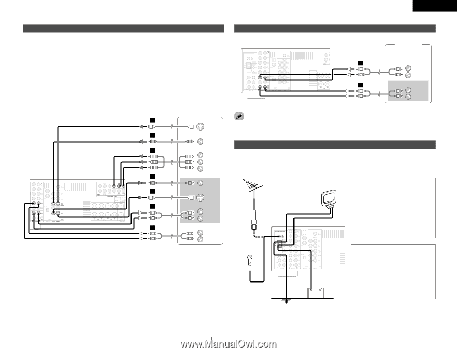
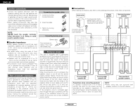
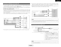
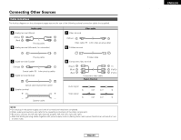
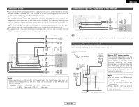
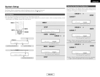
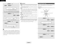
Connecting Other Sources Connecting a VCR • If you wish to perform analog dubbing from a digital source, such as a DVD recorder to an analog recorder such as a cassette deck, you will need to connect the analog inputs and outputs as shown below, in addition to the digital audio connections. • Precaution when using S-terminals This unit's S-terminals (input and output) and video pin terminals (input and output) have independent circuit structures, so that video signals input from the S-terminals are only output from the S-terminal outputs and video signals input from the pin terminals are only output from the pin terminal outputs. When connecting this unit with equipment that is equipped with S-terminals, keep the above point in mind and make connections according to the equipment's instruction manuals. • The signals input to the color difference (component) video terminals are not output from the VIDEO output terminal (yellow) or the S-Video output terminal. ENGLISH Connecting Other Sources Connecting a tape deck, CD recorder or MD recorder Tape deck / CD recorder / MD recorder A AUDIO OUT L L L R R R A AUDIO IN L L L R R R Video deck G S VIDEO OUT F VIDEO OUT H COMPONENT VIDEO OUT Y PB PR F VIDEO IN G S VIDEO IN A AUDIO IN L L L R R R A AUDIO OUT L L L R R R NOTE: • When recording to a VCR recorder, it is necessary that the type of cable used with the playback source equipment be the same type that is connected to the AVR-1506 VCR OUTPUT terminal. Example: VCR IN → S-Video cable : VCR OUT → S-Video cable VCR IN → Video cable : VCR OUT → Video cable • If humming noise is generated, move the tape deck further away from the source of such noise. Connecting the antenna terminals An FM antenna cable plug can be connected directly to the unit. Direction of broadcasting station FM antenna 75 Ω/ohm COAXIAL cable FM indoor antenna (Supplied) AM loop antenna (Supplied) Ground AM outdoor antenna Note to CATV system installer: This reminder is provided to call the CATV system installer's attention to Article 820-40 of the NEC which provides guidelines for proper grounding and, in particular, specifies that the cable ground shall be connected to the grounding system of the building, as close to the point of cable entry as practical. NOTE: • Do not connect two FM antennas simultaneously. • Even if an external AM antenna is used, do not disconnect the AM loop antenna. • Make sure the AM loop antenna lead terminals do not touch metal parts of the panel. 10 ENGLISH
-
 1
1 -
2
-
3
-
4
-
5
-
6
-
7
-
 8
8 -
 9
9 -
 10
10 -
 11
11 -
 12
12 -
 13
13 -
 14
14 -
 15
15 -
 16
16 -
 17
17 -
 18
18 -
19
-
20
-
21
-
22
-
23
-
24
-
25
-
26
-
27
-
28
-
29
-
30
-
31
-
32
-
33
-
34
-
35
-
36
-
37
-
38
-
39
-
40
-
41
-
42
-
43
-
44
-
45
-
46
-
47
-
48
-
49
-
50
-
51
-
52
-
53
 |
 |