Denon AVR-2311CI Owners Manual - English - Page 74

Rear panel

Page 74 highlights

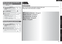
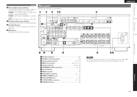
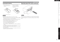
Simple version Display Q6 Tuner reception mode indicators These light according to the reception conditions when the input source is set to "HD Radio". STEREO : In the FM mode, this light when receiving analog stereo broadcasts. TUNED : Lights when the broadcast is properly tuned in. AUTO : This light when in the auto tuning mode. Q7 Recording output source indicator This lights when the REC OUT mode is selected. Q8 Decoder indicators These light when the respective decoders are operating. Q9 HD indicator This light during HD Radio reception. Rear panel See the page indicated in parentheses ( ). Q3 Q2 Q1 Q0 o ENGLISH i Basic version Advanced version qw e r q RS-232C connector 20) w HD Radio antenna terminals 19) e Analog audio connectors 16 - 19) r PRE OUT connectors 5, 33 - 35, 41) t Speaker terminals 5, 33 - 35) y COMPONENT VIDEO connectors 15, 16) u AC inlet (AC IN 5) i HDMI connectors 14) o Digital audio connectors 15 - 17) Q0 REMOTE CONTROL jacks 20) Q1 DOCK CONTROL jack 18) Q2 S-VIDEO/VIDEO connectors 15 - 18) Q3 TRIGGER OUT jack 20) t yu NOTE Do not touch the inner pins of the connectors on the rear panel. Electrostatic discharge may cause permanent damage to the unit. 71 Information

  • 1
  • 2
  • 3
  • 4
  • 5
  • 6
  • 7
  • 8
  • 9
  • 10
  • 11
  • 12
  • 13
  • 14
  • 15
  • 16
  • 17
  • 18
  • 19
  • 20
  • 21
  • 22
  • 23
  • 24
  • 25
  • 26
  • 27
  • 28
  • 29
  • 30
  • 31
  • 32
  • 33
  • 34
  • 35
  • 36
  • 37
  • 38
  • 39
  • 40
  • 41
  • 42
  • 43
  • 44
  • 45
  • 46
  • 47
  • 48
  • 49
  • 50
  • 51
  • 52
  • 53
  • 54
  • 55
  • 56
  • 57
  • 58
  • 59
  • 60
  • 61
  • 62
  • 63
  • 64
  • 65
  • 66
  • 67
  • 68
  • 69
  • 70
  • 71
  • 72
  • 73
  • 74
  • 75
  • 76
  • 77
  • 78
  • 79
  • 80
  • 81
  • 82
  • 83
  • 84
  • 85
  • 86
  • 87
  • 88
  • 89
  • 90

71
ENGLISH
Basic version
Advanced version
Simple version
Information
Rear panel
See the page indicated in parentheses ( ).
w
q
e
r
y
t
i
o
Q1
Q0
Q2
Q
3
u
q
RS-232C connector
·································································· (20)
w
HD Radio antenna terminals
·················································· (19)
e
Analog audio connectors
·················································(16 – 19)
r
PRE OUT connectors
··············································(5, 33 – 35, 41)
t
Speaker terminals
························································(5, 33 – 35)
y
COMPONENT VIDEO connectors
····································· (15, 16)
u
AC inlet (AC IN)
·········································································· (5)
i
HDMI connectors
····································································· (14)
o
Digital audio connectors
··················································(15 – 17)
Q
0
REMOTE CONTROL jacks
······················································· (20)
Q
1
DOCK CONTROL jack
······························································ (18)
Q
2
S-VIDEO/VIDEO connectors
············································(15 – 18)
Q
3
TRIGGER OUT jack
·································································· (20)
NOTE
Do not touch the inner pins of the connectors on the rear panel.
Electrostatic discharge may cause permanent damage to the unit.
Q
6
Tuner reception mode indicators
These light according to the reception conditions
when the input source is set to “HD Radio”.
STEREO
: In the FM mode, this light when
receiving analog stereo broadcasts.
TUNED
: Lights when the broadcast is properly
tuned in.
AUTO
: This light when in the auto tuning mode.
Q
7
Recording output source indicator
This lights when the REC OUT mode is selected.
Q
8
Decoder indicators
These light when the respective decoders are
operating.
Q
9
HD indicator
This light during HD Radio reception.
Display