Denon DVD 3800BDCI Owners Manual - English - Page 10
Part Names and Functions - blu ray player
 |
UPC - 083795000172
View all Denon DVD 3800BDCI manuals
Add to My Manuals
Save this manual to your list of manuals |
Page 10 highlights
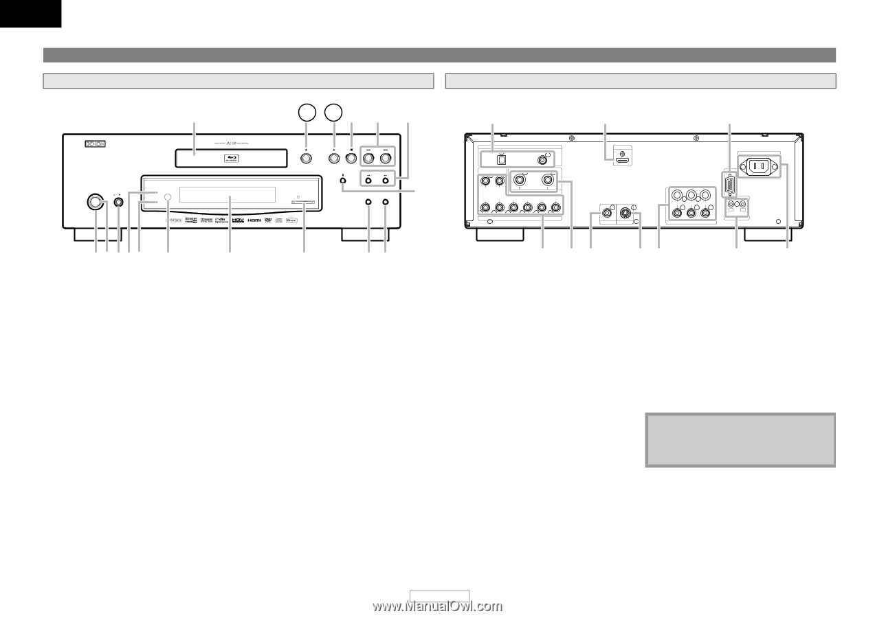
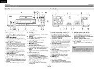
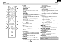
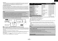
ENGLISH Introduction Part Names and Functions Front Panel 9 ON / STANDBY ON OFF Advanced AL24 VIDEO NR 10 11 12 13 14 Rear Panel 1 SD CARD HDMI RESOLUTION VIDEO NOISE REDUCTION BLU-RAY DISC PLAYER DVD-3800BDCI 15 OPTICAL DIGITAL OUT ( PCM / BITSTREAM ) COAXIAL FR FL 2ch AUDIO OUT SW C SR SL SBR SBL 7.1ch AUDIO OUT 6 HDMI OUT VIDEO OUT S VIDEO OUT Introduction 9 RS-232C AC IN Y PB/CB PR/CR COMPONENT VIDEO OUT STRAIGHT CABLE OUT IN ROOM TO ROOM REMOTE CONTROL 12 345 6 7 8 The unit can also be turned on by pressing the buttons with circled numbers. 17 16 2 34 57 8 10 1. Power indicator This indicator lights up in green when the power is on, and lights up in red in standby mode. 2. ON/STANDBY button Press to turn the unit to standby mode. In standby mode, this unit still consumes small amount of power. 3. B ON / A OFF (POWER) switch Press to turn the unit on and off. If you turn off the unit using this switch, the unit does not consume power. In this condition, this unit does not accept any button except this switch. 4. Advanced AL24 indicator Indicates that audio signals of a BD, DVD, etc., are being processed digitally with the Advanced AL24 Processing. 5. VIDEO NR indicator Indicates that video signals of a BD, DVD, etc., are being processed digitally with the DNR (Digital Noise Reduction) processing. 6. Infrared sensor window Receives signals from your remote control so that you can control the unit from a distance. 7. Display Refer to "Front Panel Display" on page 9. 8. SD CARD slot Insert an SD Memory Card, and play back the contents in it. 9. Disc tray Place a disc when opening the disc tray. 10. A (OPEN/CLOSE) button Press to open or close the disc tray. 11. B (PLAY) button Press to start or resume playback. 12. C (STOP) button Press to stop playback. 13. H / G (SKIP DOWN/UP) button Press to skip down/up titles/chapters/tracks/files. 14. h / g (FAST FORWARD/REVERSE) button Press to search forward / backward through a disc. 15. F (STILL/PAUSE) button Press to pause playback. 16. VIDEO NOISE REDUCTION button Press repeatedly to reduce the overall level of noise on the picture (DNR). Each time you press the button, the level of the DNR switches "Off" A "+1" A "+2" A "+3" A "Off". 17. HDMI RESOLUTION button Press to set the HDMI jack's video signal output mode. 1. DIGITAL OUT (OPTICAL/COAXIAL) jack Use digital audio coaxial/optical cable to connect to an AV receiver, Dolby Digital decoder or other device with a digital audio coaxial/optical input jack. 2. 7.1ch AUDIO OUT jacks Use an RCA audio cable to connect these jacks to the 7.1-channel audio input jacks of your amplifier with 7.1-channel input terminals. 3. 2ch AUDIO OUT jacks Use an RCA audio cable to connect these jacks to the 2-channel audio input jacks of your amplifier with 2- channel input terminals. 4. VIDEO OUT jack Use an RCA video cable to connect to a TV monitor, AV receiver or other device. 5. S VIDEO OUT jack Use an S-video cable to connect to the S-video input jack of external device. 6. HDMI OUT jack Use an HDMI cable to connect to a display with an HDMI input jack. 7. COMPONENT VIDEO OUT jacks Use a component video cable to connect to a display device with component input jacks. 8. REMOTE CONTROL OUT / IN jacks Connecting the DENON Satellite Remote Control to these jacks enables you to operate more than one DENON components with one remote control. 9. CONTROL CONNECTOR (RS-232C) This is a terminal for future system extension. 10. AC IN Terminal Use to connect the AC cord to supply the power. Note • Do not touch the inner pins of the jacks on the rear panel. Electrostatic discharge may cause permanent damage to the unit. 7 ENGLISH
-
 1
1 -
2
-
3
-
4
-
 5
5 -
 6
6 -
 7
7 -
 8
8 -
 9
9 -
 10
10 -
 11
11 -
 12
12 -
 13
13 -
 14
14 -
 15
15 -
16
-
17
-
18
-
19
-
20
-
21
-
22
-
23
-
24
-
25
-
26
-
27
-
28
-
29
-
30
-
31
-
32
-
33
-
34
-
35
-
36
-
37
-
38
-
39
-
40
-
41
-
42
-
43
-
44
 |
 |