Dewalt DCP580B Instruction Manual - Page 13
Trigger Switch Fig. 2, Adjusting the Planing Depth Fig. 2
 |
View all Dewalt DCP580B manuals
Add to My Manuals
Save this manual to your list of manuals |
Page 13 highlights
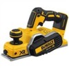
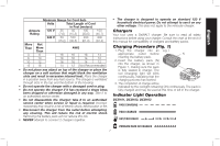
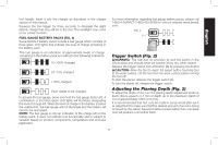
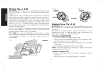
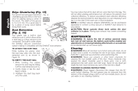
English tool handle. Insert it into the charger as described in the charger section of this manual. Squeeze the tool trigger for three seconds to dissipate the slight electric charge that may still be in the tool. The worklight may come on for a brief moment. FUEL GAUGE BATTERY PACKS (FIG. 4) Some DeWALT battery packs include a fuel gauge which consists of three green LED lights that indicate the level of charge remaining in the battery pack. The fuel gauge is an indication of approximate levels of charge remaining in the battery pack according to the following indicators: 75-100% charged 51-74% charged < 50% charged Pack needs to be charged To actuate the fuel gauge, press and hold the fuel gauge button (P). A combination of the three green LED lights will illuminate designating the level of charge left. When the level of charge in the battery is below the usable limit, the fuel gauge will not illuminate and the battery will need to be recharged. NOTE: The fuel gauge is only an indication of the charge left on the battery pack. It does not indicate tool functionality and is subject to variation based on product components, temperature and end-user application. For more information regarding fuel gauge battery packs, please call 1-800-4-DeWALT (1-800-433-9258) or visit our website www.dewalt. com. FIG. 4 P Trigger Switch (Fig. 2) WARNING: This tool has no provision to lock the switch in the ON position and should never be locked ON by any other means. Release the trigger switch lock-off button (B) by pressing the button. CAUTION: Allow the tool to reach full speed before touching tool to the work surface. Lift the tool from the work surface before turning the tool off. To start the planer, depress the trigger switch (A). To turn the planer off, release the trigger switch. Adjusting the Planing Depth (Fig. 2) To adjust the depth of cut, turn the planing depth adjustment knob (J). Each click is equal to 0.1 mm of depth up to the maximum depth of cut of approximately 5/64" (2.0 mm). It is recomm ended that test cuts be made in scrap wood after each re-adjustment to make sure that the desired amount of wood is being removed by the planer. Several shallow passes (rather than one deep one) will produce a smoother finish. 11
-
 1
1 -
2
-
3
-
4
-
5
-
6
-
7
-
 8
8 -
 9
9 -
 10
10 -
 11
11 -
 12
12 -
 13
13 -
 14
14 -
 15
15 -
 16
16 -
 17
17 -
 18
18 -
19
-
20
-
21
-
22
-
23
-
24
-
25
-
26
-
27
-
28
-
29
-
30
-
31
-
32
-
33
-
34
-
35
-
36
-
37
-
38
-
39
-
40
-
41
-
42
-
43
-
44
-
45
-
46
-
47
-
48
-
49
-
50
-
51
-
52
-
53
-
54
-
55
-
56
-
57
-
58
-
59
-
60
-
61
-
62
-
63
-
64
 |
 |