Dewalt DW0811LR Instruction Manual - Page 6
Accuracy Check and Calibration
 |
View all Dewalt DW0811LR manuals
Add to My Manuals
Save this manual to your list of manuals |
Page 6 highlights
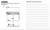
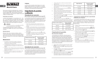
EN User Manual Cleaning Exterior plastic parts may be cleaned with a damp cloth. Although these parts are solvent resistant, NEVER use solvents. Use a soft, d ry cloth to remove moisture from the tool before storage. Once the ceiling mount is secured, its steel plate provides a surface to which the magnetic pivot bracket G can be attached. The position of the laser can then be fine-tuned by sliding the magnetic pivot bracket up or down on the wall mount. Accuracy Check and Calibration Checking Accuracy - Horizontal Beam, Scan Direction (See figure 7 ) Using the Lasers with Accessories The lasers are equipped with 1/4" - 20 and 5/8" - 11 female threads on the bottom of the unit. This thread is to accommodate current or future DeWALT accessories. Only use DeWALT accessories specified for use with this product. Follow the directions included with the accessory. CAUTION: The use of any other accessory not recommended for use with this tool could be hazardous. If you need any assistance in locating any accessory, please contact your nearest DeWALT service center or go to www.dewalt.com on the Internet. Leveling the Lasers As long as the laser is properly calibrated, the laser is selfleveling. Each laser is calibrated at the factory to find level as long as it is positioned on a flat surface within average ± 4° of level. No manual adjustments are required. Checking the horizontal scan calibration of the laser requires two walls 9m (30') apart. It is important to conduct a calibration check using a distance no shorter than the distance of the applications for which the tool will be used. 1. Attach the laser to a wall using its pivot bracket, with the laser facing straight ahead toward the opposing wall (0 degree position). 2. Turn on the laser's horizontal beam and front vertical beam and mark the beam position on the opposing wall directly across from the laser. Always mark the center of the beam's thickness. 3. Pivot the laser 180 degrees and mark the beam position on the opposing wall. 4. Measure the vertical distance between the lowest mark A and the highest mark B . If the measurement is greater than the values shown below, the laser must be serviced at an authorized service center. Distance Between Walls Allowable Distance Between Marks Maintenance • To maintain the accuracy of your work, check the laser often to make sure it is properly calibrated. See Field Calibration Check. • Calibration checks and other maintenance repairs may be performed by DeWALT service centers. • When not in use, store the laser in the kit box provided. Do not store your laser at temperatures below -5˚F (-20˚C ) or above 140˚F (60˚C). • Do not store your laser in the kit box if the laser is wet. The laser should be dried first with a soft dry cloth prior to storage. 30' (9m) 40' (12m) 50' (15m) 1/8" (3.0mm) 5/32" (4.0mm) 7/32" (5.0mm) Checking Accuracy - Horizontal Beam, Pitch Direction (See figure 8 ) Checking the horizontal pitch calibration of the laser requires a single wall at least 30' (9m) long. It is important to conduct a calibration check using a distance no shorter than the distance of the applications for which the tool will be used. 10 1. Attach the laser to one end of a wall using its pivot bracket. 2. Turn on the laser's horizontal beam and pivot the laser toward the opposite end of the wall and approximately parallel to the adjacent wall. 3. Mark the center of the beam at two locations ( c , d ) at least 30' (9m) apart. 4. Reposition the laser to the opposite end of the wall. 5. Turn on the laser's horizontal beam and pivot the laser back toward the first end of the wall and approximately parallel to the adjacent wall. 6. Adjust the height of the laser so that the center of the beam is aligned with the nearest mark d . 7. Mark the center of the beam e directly above or below the farthest mark c . 8. Measure the distance between these two marks ( c , e ). If the measurement is greater than the values shown below, the laser must be serviced at an authorized service center. Distance Between Walls Allowable Distance Between Marks 30' (9m) 1/4" (6.0mm) 40' (12m) 5/16" (8.0mm) 5. Measure the distance between the two ceiling marks ( h , j ). If the measurement is greater than the values shown below, the laser must be serviced at an authorized service center. Ceiling Height Allowable Distance Between Marks 8' (2.5m) 1/16" (1.5mm) 10' (3m) 3/32" (2.0mm) 14' (4m) 1/8" (2.5mm) 20' (6m) 5/32' (4m) 30' (9m) 1/4' (6m) Checking 90º Accuracy Between Vertical Beams (DW089LR/G) (See Figure 10 ) Checking 90º accuracy requires an open floor area at least 33' x 18' (10m x 5m). Refer to Figure 9 for the position of the laser at each step and for the location of the marks made at each step. Always mark the center of the beams' thickness. 50' (15m) 13/32" (10.0mm) Checking Accuracy - Vertical Beam (See Figure 9 ) Checking the vertical (plumb) calibration of the laser can be most accurately done when there is a substantial amount of vertical height available, ideally 30' (9m), with one person on the floor positioning the laser and another person near a ceiling to mark the position of the beam. It is important to conduct a calibration check using a distance no shorter than the distance of the applications for which the tool will be used. 1. Place the laser on the floor and turn on both vertical beams. 2. Mark two positions where the beams cross on the floor ( f , g ) and also on the ceiling h . Always mark the center of the beams' thickness. 3. Rotate the laser 180 degrees, and reposition it close to the second mark g so the beam crossing is exactly on the original marks ( f , g ) on the floor. 4. Mark the position where the beams cross on the ceiling j . 1. Set up the laser in one corner of the floor and turn on the side vertical beam. 2. Mark the center of the beam at three locations ( a , b , c )on the floor along the side laser line. Mark b should be at the midpoint of the laser line. 3. Move the laser to mark b and turn on both vertical beams. 4. Position the beam crossing precisely at mark b , with the side beam aligned with mark c . 5. Mark a location d along the front vertical beam at least 5m (18') away from the unit. 6. Rotate the laser cross over mark b so that the side vertical beam now passes through mark b , d . 7. Mark the location e where the side vertical beam passes by mark d . 8. Measure the distance between marks d and e . If the measurement is greater than the values shown below, the laser must be serviced at an authorized service center. 11
-
 1
1 -
 2
2 -
 3
3 -
 4
4 -
 5
5 -
 6
6 -
 7
7 -
 8
8 -
 9
9 -
 10
10 -
 11
11 -
 12
12 -
13
-
14
-
15
-
16
-
17
-
18
-
19
-
20
-
21
-
22
-
23
-
24
 |
 |