Electrolux E48DF76EPS Installation Instructions - Page 31
STEP 7, Replace Main Orifices
 |
View all Electrolux E48DF76EPS manuals
Add to My Manuals
Save this manual to your list of manuals |
Page 31 highlights
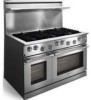
Professional Series Range LPG Conversion Kit STEP 7 Replace Main Orifices 7-1 Remove the two screws that hold the left rear burner base to the stove chassis. 7-2 Hold the shutter connector with the 8" adjustable wrench. Remove the air shutter using the 6" adjustable wrench. 7-3 Hold the shutter connector with the 8" adjustable wrench. Remove the main orifice from the shutter connector using the 10 mm open-end wrench. 7-4 Replace the main orifice with the appropriate size from Table 7-1. Match both the model number and the burner location. The main orifice size is stamped on its side. The shutter and the burner base will be re-assembled after pressure testing. 7-5 Check to make sure that the compression nut is tightened into the back of the shutter connector. 7-6 Repeat steps 7-1 through 7-5 for the remaining burners. Burner E30DF74EPS E36DF76EPS E48DF76EPS Location (30-Inch) (36-Inch) (48-Inch) Left Rear 84 112 112 Left Front 111 86 86 Right Rear 111 86 86 Right Front 118 112 112 Center Rear - 118 118 Center Front - 118 118 Table 7-1 Main Orifice Sizes (X 100 mm) Burner Base Compression Nut Main Orifice Air Shutter (remove) Shutter Connector Figure 7-1 Main Orifice Conversion Page 7
-
 1
1 -
2
-
3
-
4
-
5
-
6
-
7
-
8
-
9
-
10
-
11
-
12
-
13
-
14
-
15
-
16
-
17
-
18
-
19
-
20
-
21
-
22
-
23
-
24
-
25
-
 26
26 -
 27
27 -
 28
28 -
 29
29 -
 30
30 -
 31
31 -
 32
32 -
 33
33 -
 34
34 -
 35
35 -
 36
36
 |
 |
